Product Safety - LPG Conversion Induction System Damage

| Subject: | 02044 - LPG Conversion Induction System Damage |
| Models: | 1999-2000 Chevrolet Medium Duty C-Series |
| 1999 Chevrolet Medium Duty School Bus Chassis |
| 1999-2000 GMC Medium Duty C-Series and School Bus Chassis |
| Equipped with a 7.4L Gas Engine and IMPCO LPG Conversion Kit |
Condition
General Motors has decided that a defect which relates to motor vehicle safety exists in certain 1999-2000 model year Chevrolet Medium Duty C-Series trucks; 1999 model year Chevrolet Medium Duty school bus chassis; and 1999-2000 model year GMC Medium Duty C-Series trucks and school bus chassis equipped with a 7.4L gas engine and an IMPCO LPG conversion kit. Some of these vehicles may have engine backfires with sufficient force to damage the engine air intake system and the air cleaner filter element. If the damaged air cleaner parts are dislodged from their normal position, these parts may come in contact with the hot exhaust manifold and/or hot exhaust gas recirculation (EGR) valve tube resulting in a possible engine compartment fire.
Correction
Dealers are to install a redesigned mixer bonnet and air cleaner housing cover, selective upgrades in various connections related to the air induction system, and if needed, a new air cleaner filter.
Vehicles Involved
Involved are certain 1999-2000 model year Chevrolet Medium Duty C-Series trucks; 1999 model year Chevrolet Medium Duty school bus chassis; and 1999-2000 model year GMC Medium Duty C-Series trucks and school bus chassis equipped with a 7.4L gas engine and an IMPCO LPG conversion kit and built within these VIN breakpoints.
Year | Division | Model | Plant | From | Through |
|---|---|---|---|---|---|
1999 | Chevrolet | C-Series | Janesville | XJ100011 | XJ108756 |
2000 | Chevrolet | C-Series | Janesville | YJ500083 | YJ527753 |
1999 | Chevrolet | School Bus | Janesville | XJ105845 | XJ106052 |
1999 | GMC | C-Series | Janesville | XJ500730 | XJ519602 |
2000 | GMC | C-Series | Janesville | YJ500701 | YJ528617 |
1999 | GMC | School Bus | Janesville | XJ511748 | XJ512521 |
2000 | GMC | School Bus | Janesville | YJ514988 | YJ528550 |
Important: Dealers should confirm vehicle eligibility through GMVIS (GM Vehicle Inquiry System) before beginning recall repairs. [Not all vehicles within the above breakpoints may be involved.]
Involved vehicles have been identified by Vehicle Identification Number. Computer listings containing the complete Vehicle Identification Number, customer name and address data have been prepared, and are being furnished to involved dealers with the recall bulletin. The customer name and address data furnished will enable dealers to follow-up with customers involved in this recall. Any dealer not receiving a computer listing with the recall bulletin has no involved vehicles currently assigned.
These dealer listings may contain customer names and addresses obtained from Motor Vehicle Registration Records. The use of such motor vehicle registration data for any other purpose is a violation of law in several states/provinces/countries. Accordingly, you are urged to limit the use of this listing to the follow-up necessary to complete this recall.
Parts Information
Parts required to complete this recall are to be obtained from two sources.
Important: Due to the uniqueness and small number of vehicles involved, and due to limited parts availability, dealers should not order kits for use as shelf stock. Kits are to be ordered after scheduling an appointment with the customer.
P/N | Description | Qty/Vehicle |
|---|---|---|
12346067 | Adhesive, Black Toughened | 1 (1 tube services 2 vehicles) |
Order directly by calling 1-800-816-8691. DO NOT ORDER THIS KIT FROM GMSPO. | ||
|---|---|---|
P/N | Description | Qty/Vehicle |
105774 | MY 1999 - Induction System Retro Kit | 1 |
105775 | MY 2000 - Induction System Retro Kit - w/Standard Emissions | 1 |
105776 | MY 2000 - Induction System Retro Kit - w/Low NOx Emissions (see Step 49 of the service procedure) | 1 |
Service Procedure
Important: With the exception of the black toughened adhesive (P/N 12346067), all the parts necessary to perform this recall are included in the service kit described in the Parts Information section of this recall bulletin.
- Open the hood.
- Remove the retaining clips and remove both the left and right wheelhouse panels.
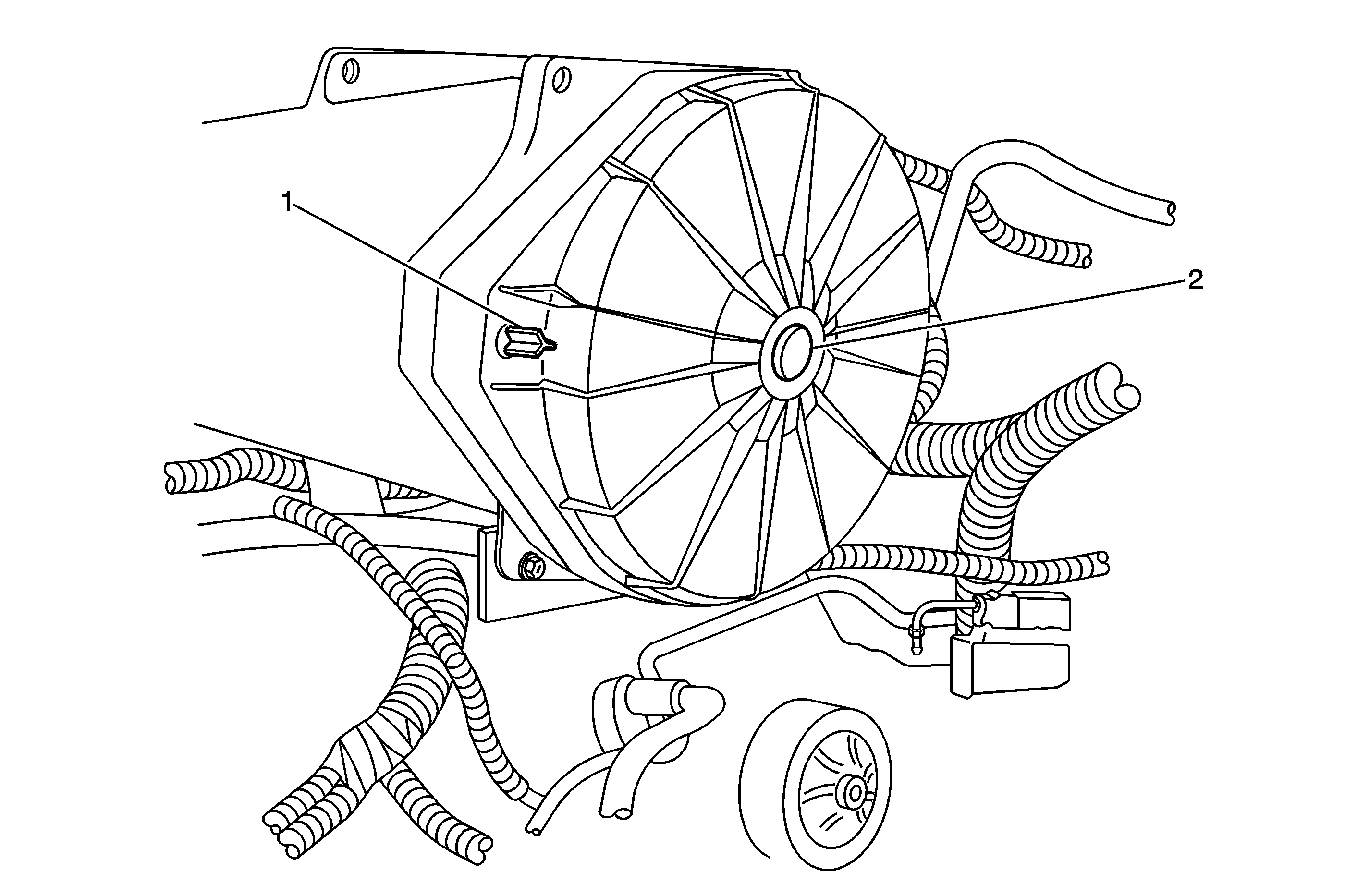
- Remove the two hand screws (1) attaching the cover to the air cleaner housing and remove the cover and filter. Do no reuse the two hand screws.
- Remove the plastic push-in fastener (2) from the center of the air cleaner cover. Do not reuse the fastener. At this point, the air cleaner cover can be separated from the air filter holder.
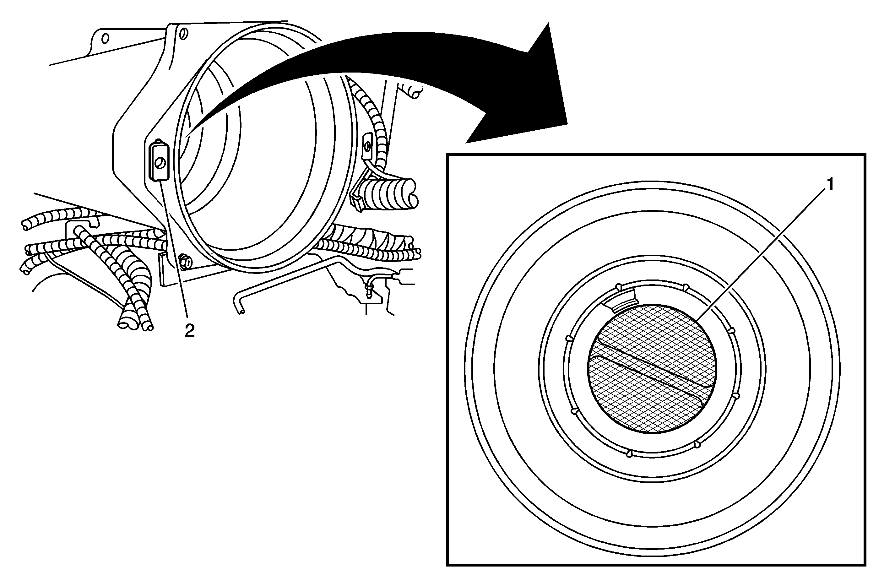
- Look into the air cleaner housing on the engine and inspect the screen (1) located inside the mass air flow (MAF) sensor on the opposite side. If the screen is damaged, replace the MAF sensor and then continue.
- Remove the two plastic insert nuts (2) from the air cleaner housing. Do not reuse the nuts. The insert nuts are what the air cleaner cover attaching screws thread to.
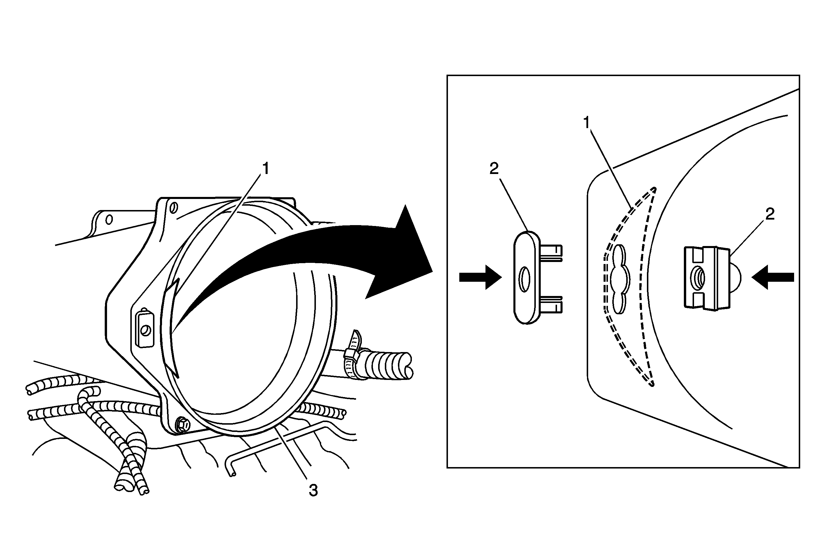
- Position one steel reinforcement (1) on the INSIDE of the air cleaner housing so that the opening in the reinforcement aligns with the hole in the housing.
- While holding the steel reinforcement in position inside of the air cleaner housing, install the new two-piece insert nut (2) into the housing (3). The two halves of the insert nut will snap or lock together when properly installed and will hold the reinforcement in position.
- Repeat Steps 6 and 7 on the other side of the air cleaner housing.
- Inspect the air cleaner cover and filter for damage. Replace only if damage is found.
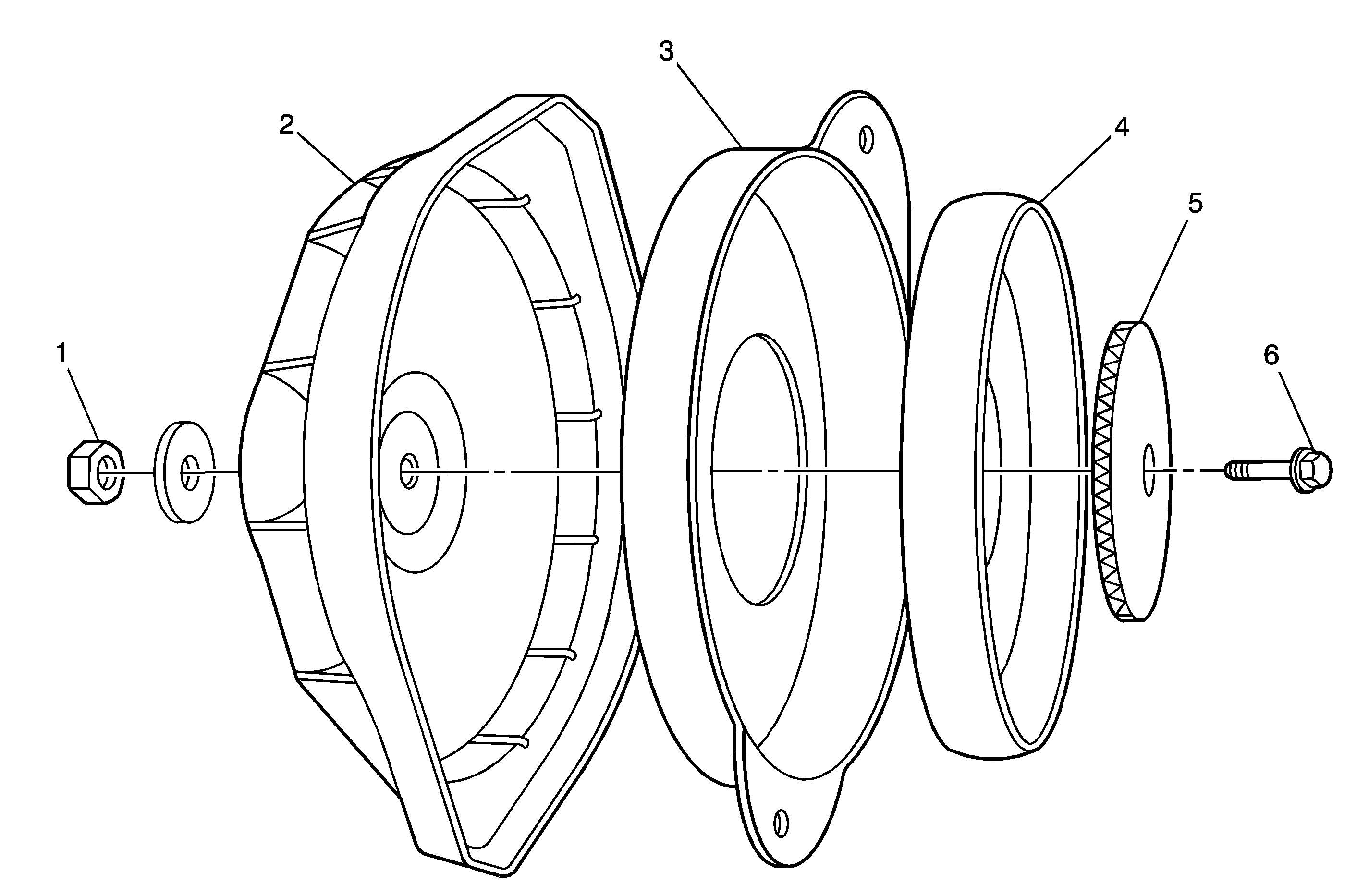
- Assemble the air cleaner cover (2), new cover reinforcement from the service kit (3), original air filter holder (4), neoprene rubber insert (5), bolt (6), washer, and nut (1), as shown. Hand tighten the bolt and nut.
- Install the air filter element inside of the air cleaner housing.
- Install the air cleaner cover assembly (3) to the air cleaner housing (2), and install the two new attaching bolts and washers (1).
- Remove the PCV valve (3) from the grommet (2) in the left rocker cover.
- Using a shop towel, remove any oil, grease, or dirt from the outside of the PCV valve and the hole in the grommet.
- Inspect the grommet for damage and replace, if necessary.
- Install a clamp (4) on the hose where it connects to the PCV valve. Hand tighten only.
- Install a clamp (1) on the other end of the PCV valve hose where it connects to the intake manifold plenum. Hand tighten only.
- Apply a few drops of black toughened adhesive around the base of the PCV valve and immediately install the valve in the grommet in the rocker cover.
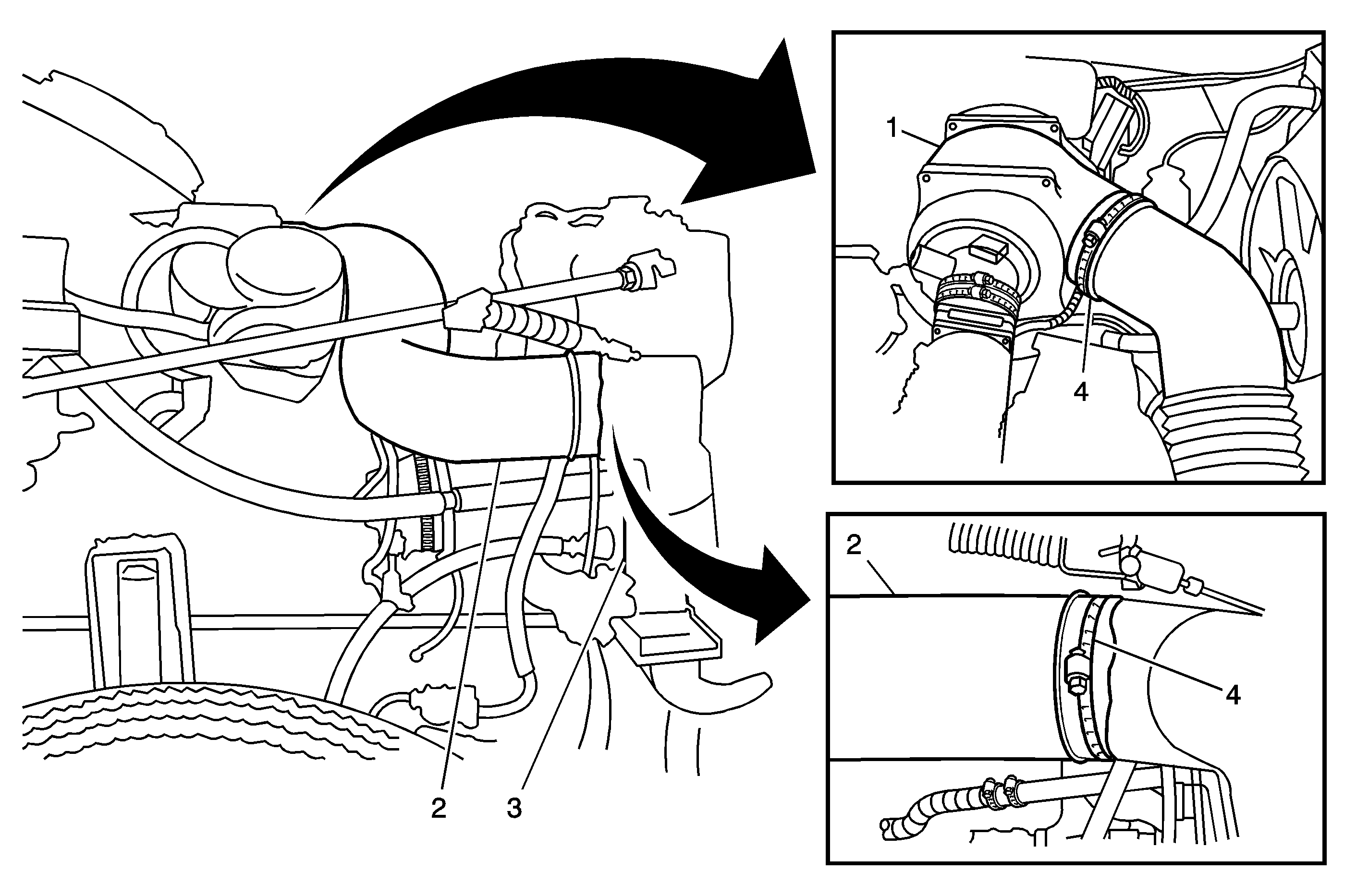
- Remove the plastic air cleaner inlet duct located between the air cleaner housing and the radiator support.
- Remove the clamp (4) attaching the small hose to the mixer bonnet cover (3) and disconnect the hose.
- Remove the clamp (2) attaching the mixer bonnet cover to the MAF sensor (1).
- Disconnect the electrical connector from the mixer bonnet cover.
- Remove the six screws attaching the mixer bonnet cover to the base plate.
- Separate the mixer bonnet cover from the MAF sensor. do not reuse the cover.
- Remove the wiring grommet (2) from the hole in the mixer baseplate (1).
- Using a shop towel, clean or remove any oil, grease, or dirt from the grommet and hole.
- Apply a few drops of black toughened adhesive to the grommet and immediately reinstall it into the mixer baseplate.
- Remove the air temperature sensor and grommet from the old mixer bonnet cover.
- Install the air temperature sensor grommet in the NEW mixer bonnet cover and then install the sensor.
- Install the NEW mixer bonnet cover to the MAF sensor and position it on the baseplate. Install the six screws.
- Install the clamp on the MAF sensor. Hand tighten only.
- Connect the small hose to the mixer bonnet cover and install the clamp. Hand tighten only.
- Connect the electrical connector to the sensor in the mixer bonnet cover.
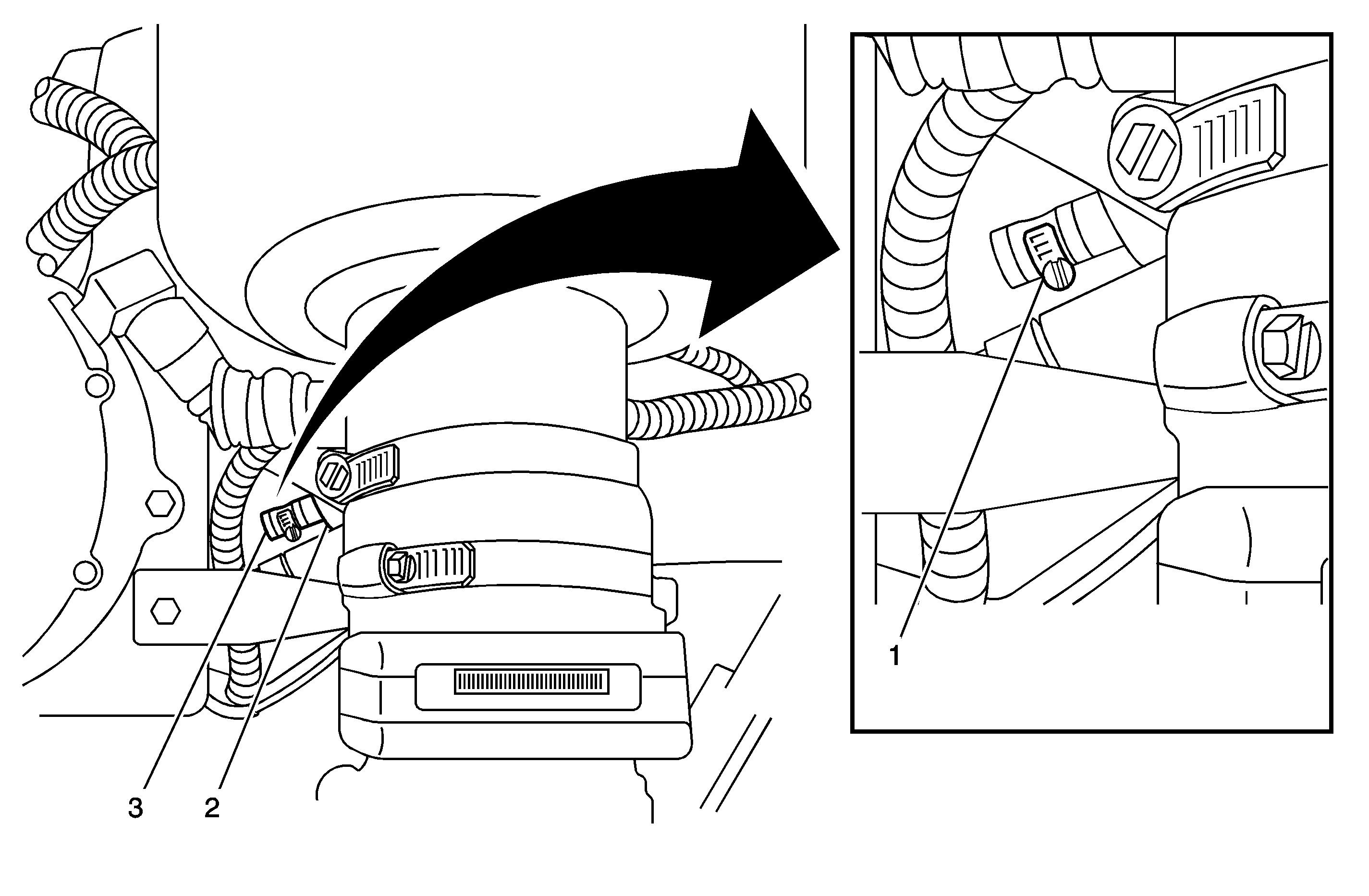
- Inspect the vacuum fitting (3) located in the intake manifold plenum (2) and verify that it is plugged off. The fitting can best be seen by looking directly downward between the LPG regulator and the air cleaner outlet to the MAF sensor. The fitting is located on the rear of the throttle body mounting flange of the intake manifold. If the plug is missing, install the new one that is included in the kit.
- Install a hose clamp (1) on the plug to secure it to the fitting. Hand tighten only.
- Install one clamp (4) on each end of the plastic air cleaner inlet duct (2) and install the duct between the air cleaner housing (1) and the radiator support (3). Hand tighten the two clamps.
- Disconnect all eight spark plug wires from the spark plugs and coils.
- Remove the plastic conduits and heat shields from the spark plug wires and install them on the new spark plug wires. Do not reuse the old spark plug wires.
- Remove all eight spark plugs and do not reuse.
- Inspect the gap on all eight new spark plugs and verify that they are set to 0.035 in.
- Install the eight new spark plugs.
- Install the eight new plug wires on the coils and spark plugs.
- Install the left and right wheelhouse panels and the retaining clips.
- If a new Vehicle Emissions Control Information Label is included in the kit you received for the vehicle you are working on, remove the old Vehicle Emissions Control Information Label located on the air cleaner housing. If the label is not included in the kit, proceed to Step 48.
- Using isopropyl alcohol or equivalent, clean the top of the air cleaner housing to remove all traces of the old label.
- Install the new emissions label in the same location as the old label on the air cleaner housing.
- Install the new Spark Plug Information Label on top of the air cleaner housing, next to the Vehicle Emission Control Label, if applicable.
- Using a Tech 2, verify the calibration in the Powertrain Control Module (PCM).
- Install the GM Recall Identification Label.
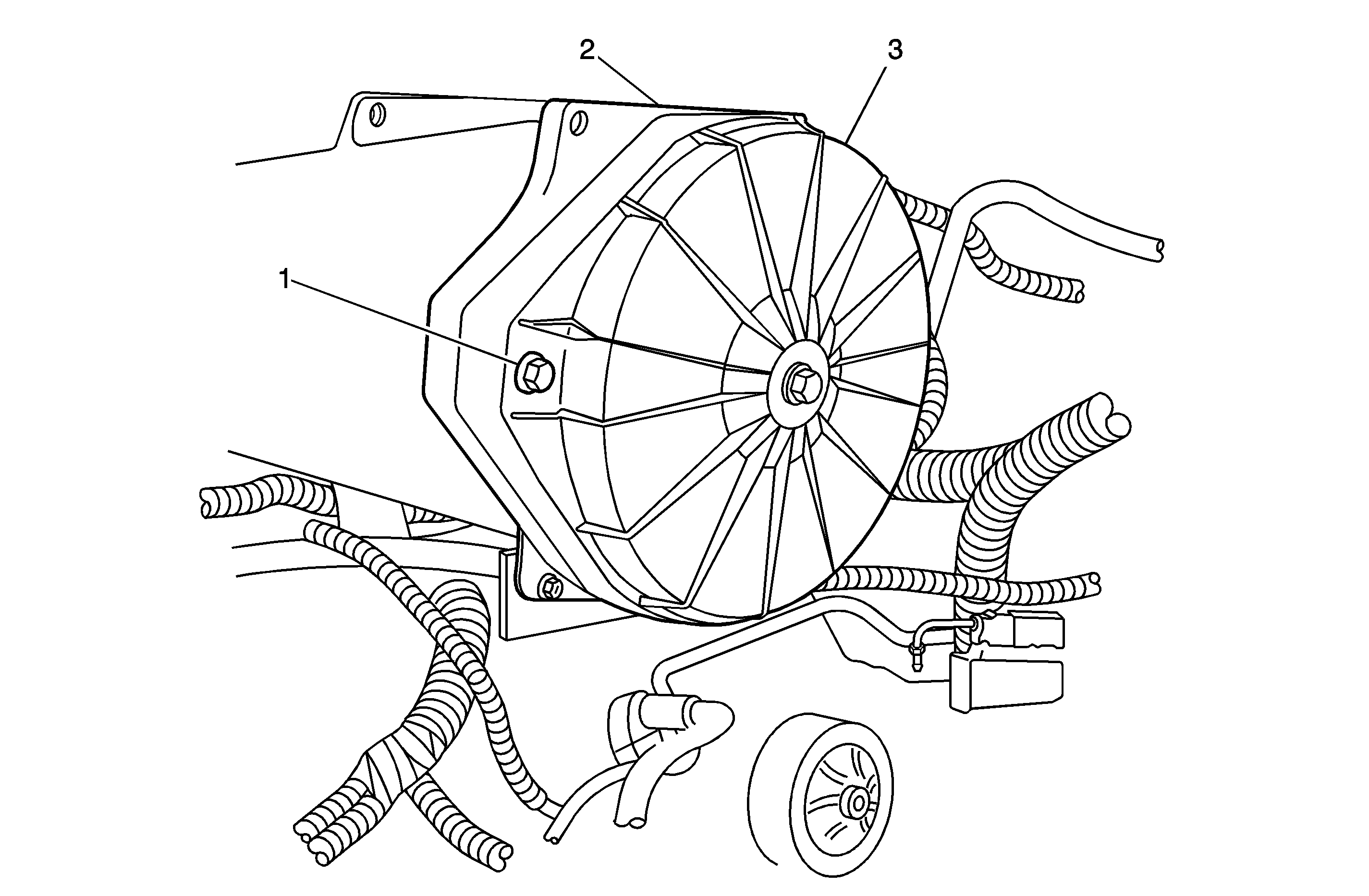
Important: The new attaching bolts described in the next step replace the two hand screws removed earlier in this procedure.
Tighten
Tighten to 3 N·m (27 lb in).
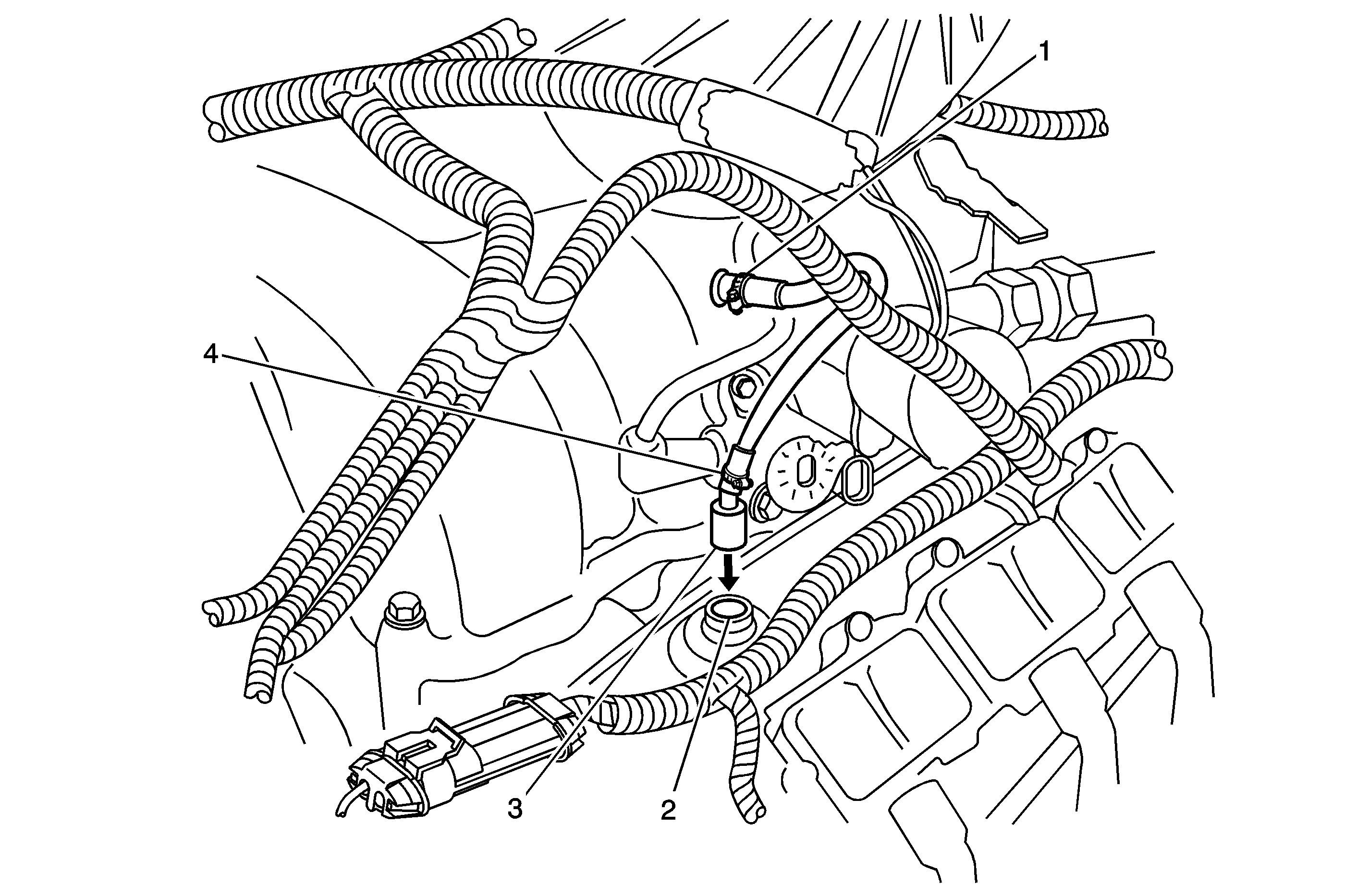
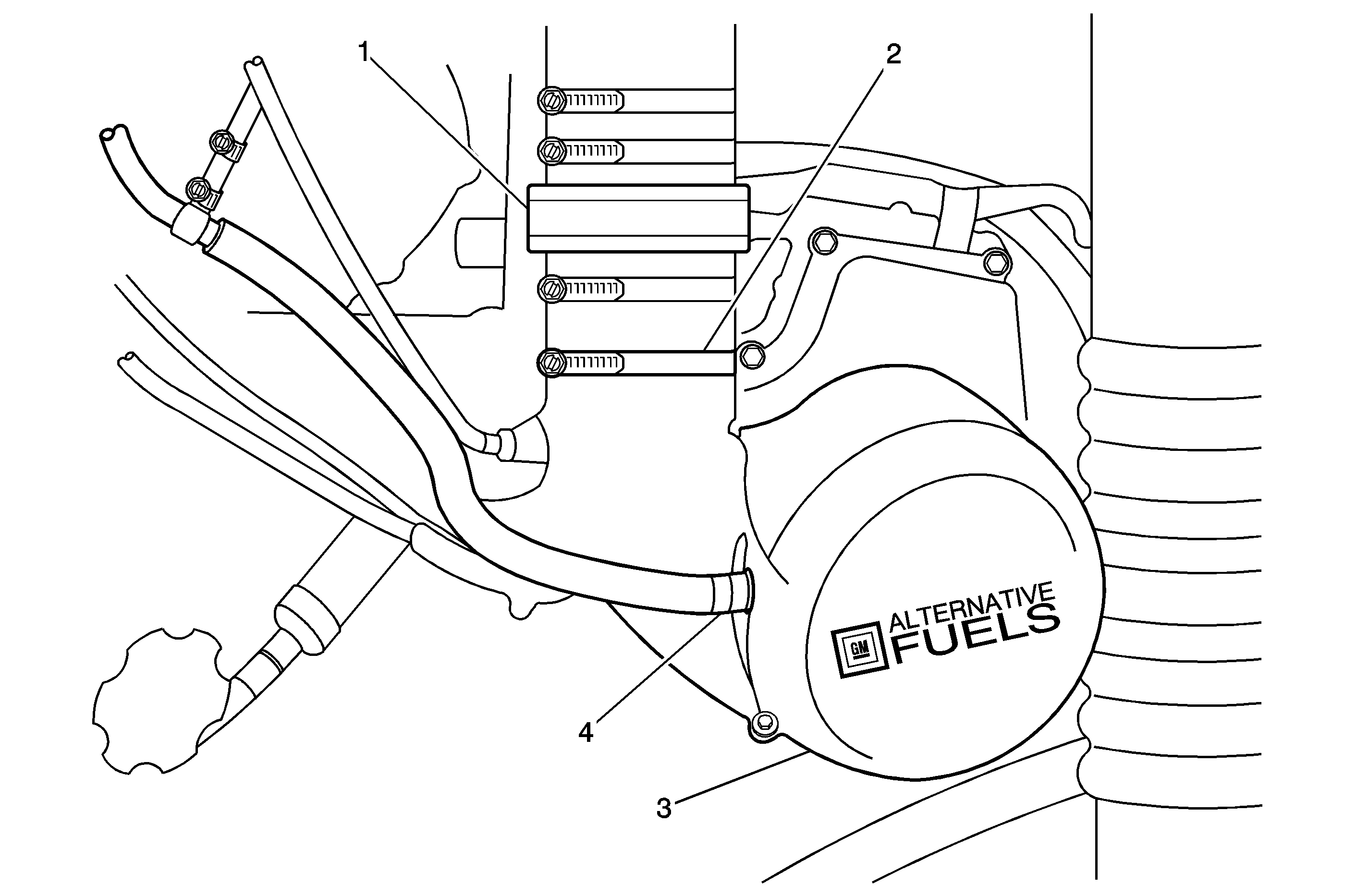
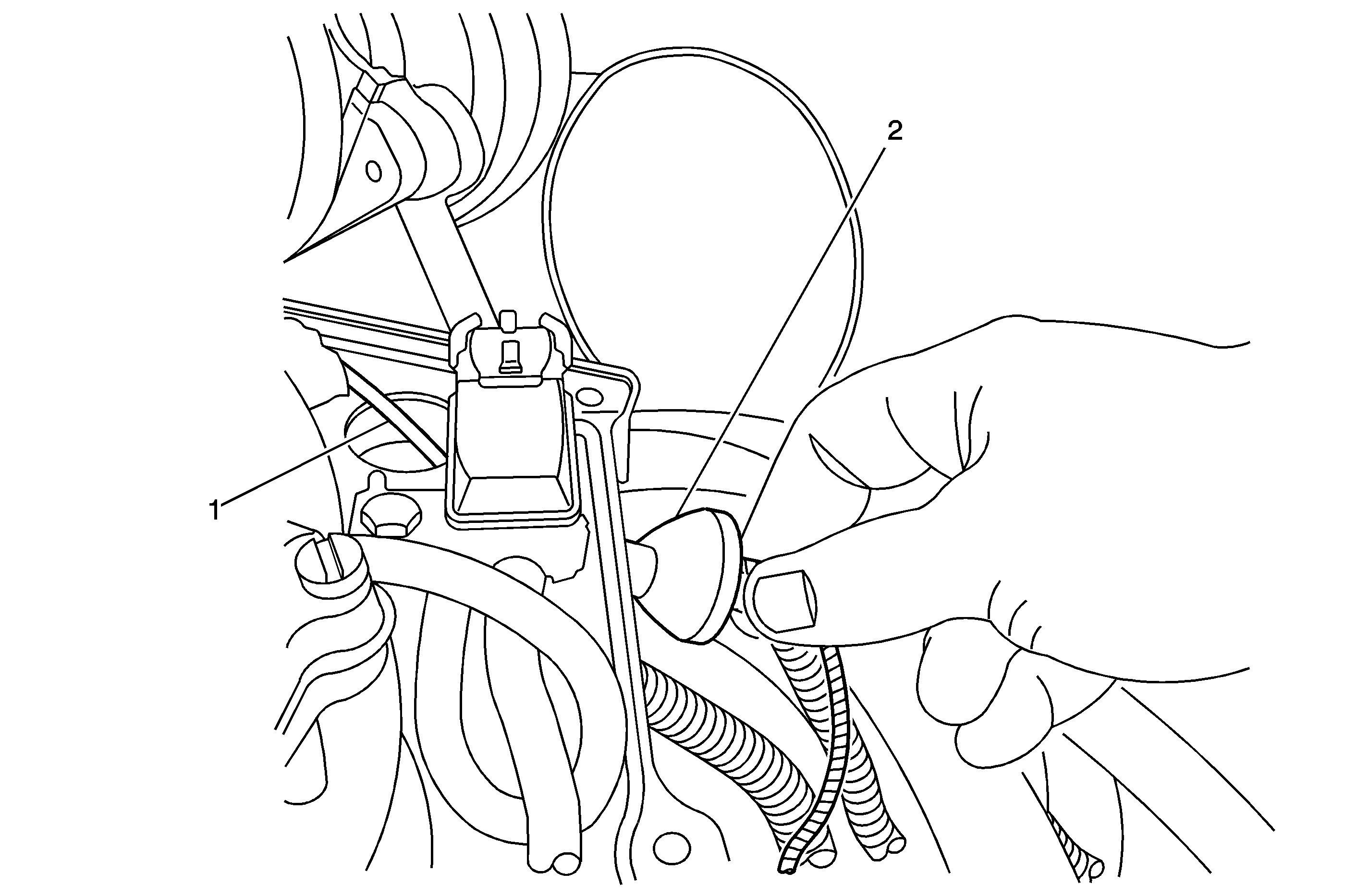
Important: The new mixer bonnet cover being installed in the next step comes complete with pressure relief devices.
Tighten
Tighten the screws to 12 N·m (106 lb in).
Important: Each new spark plug being installed in the next step must have its gap set to 0.035 in. Because these spark plugs are used in other applications, their gaps may be preset to another specification, which is NOT correct for this engine. Do not assume that they were gapped correctly when manufactured. Check the gap on each spark plug before installing.
Important: When installing the new spark plugs in the next step, make sure that the porcelain (white) section is kept clean and free of oil, grease or dirt.
Tighten
Tighten to 20 N·m (15 lb ft).
| • | Model year 2000 Low NOx vehicles: If the vehicle you are working on has one of the following VINs, it should have a software calibration number ending in 61, 62, 63, 64, 65, or 66. If it does NOT have a calibration number ending in one of these numbers, it will be necessary to reprogram the PCM. |
| - | 1GBM7H1B8YJ501032 |
| - | 1GDM7H1B7YJ528275 |
| - | 1GDM7H1B2YJ528068 |
| - | 1GDM7H1B8YJ528429 |
| - | 1GDK7H1B8YJ528129 |
| - | 1GDP7H1B3YJ528528 |
| - | 1GDK7H1B7YJ528137 |
| • | Model year 1999 and 2000 Standard Emission vehicles: These vehicles should NOT have a software calibration number ending in 61, 62, 63, 64, 65, or 66. If it DOES have a calibration number ending in one of these numbers, reprogram the PCM. |
Recall Identification Label
Place a Recall Identification Label on each vehicle corrected in accordance with the instructions outlined in this Product Recall Bulletin. Each label provides a space to include the recall number and the five (5) digit dealer code of the dealer performing the recall service. This information may be inserted with a typewriter or a ball point pen.
Put the Recall Identification Label on a clean and dry surface of the radiator core support in an area that will be visible to people servicing the vehicle. When installing the Recall Identification Label, be sure to pull the tab to allow the adhesion of the clear protective covering. Additional Recall Identification Labels for US dealers can be obtained from Dealer Support Materials by either ordering on the web from DWD Store, gm-dealerworld.com, or calling 1-866-700-0001 (Monday-Friday, 8:00 am to 5:00 pm EST). Ask for Item Number S-1015 when ordering.
Claim Information
Submit a Product Recall Claim with the information indicated below:
Repair Performed | Part Count | Part No. | Parts Allow | CC-FC | Labor Op | Labor Hours* | Net Item |
|---|---|---|---|---|---|---|---|
Retrofit Induction System (Inc. Reprogram, If Req'd) | -- | -- | ** | MA-96 | V0909 | 1.3 | *** |
* -- For Program Administrative Allowance, add 0.1 hours to the "Labor Hours". ** -- The "Parts Allowance" should be the sum total of the current GMSPO Dealer net price plus applicable Mark-Up for the adhesive needed to complete the repair. *** - The amount identified in the "Net Item" column should represent the sum total of the current GMSPO Dealer net price plus applicable Mark-Up for adhesive needed to perform the required repairs. | |||||||
Refer to the General Motors WINS Claims Processing Manual for details on Product Recall Claim Submission.
Customer Notification
Customers will be notified of this recall on their vehicles by General Motors (see copy of customer letter included with this bulletin).
Dealer Recall Responsibility
The US National Traffic and Motor Vehicle Safety Act provides that each vehicle which is subject to a recall of this type must be adequately repaired within a reasonable time after the customer has tendered it for repair. A failure to repair within sixty days after tender of a vehicle is prima facie evidence of failure to repair within a reasonable time. If the condition is not adequately repaired within a reasonable time, the customer may be entitled to an identical or reasonably equivalent vehicle at no charge or to a refund of the purchase price less a reasonable allowance for depreciation. To avoid having to provide these burdensome remedies, every effort must be made to promptly schedule an appointment with each customer and to repair their vehicle as soon as possible. In the recall notification letters, customers are told how to contact the US National Highway Traffic Safety Administration if the recall is not completed within a reasonable time.
All unsold new vehicles in dealers' possession and subject to this recall MUST be held and inspected/repaired per the service procedure of this recall bulletin BEFORE customers take possession of these vehicles.
Dealers are to service all vehicles subject to this recall at no charge to customers, regardless of mileage, age of vehicle, or ownership, from this time forward.
Customers who have recently purchased vehicles sold from your vehicle inventory, and for which there is no customer information indicated on the dealer listing, are to be contacted by the dealer. Arrangements are to be made to make the required correction according to the instructions contained in this bulletin. This could be done by mailing to such customers a copy of the customer letter accompanying this bulletin. Recall follow-up cards should not be used for this purpose, since the customer may not as yet have received the notification letter.
In summary, whenever a vehicle subject to this recall enters your vehicle inventory, or is in your dealership for service in the future, please take the steps necessary to be sure the recall correction has been made before selling or releasing the vehicle.
December, 2002Dear General Motors Customer:
This notice is sent to you in accordance with the requirements of the National Traffic and Motor Vehicle Safety Act.
Reason For This Recall
General Motors has decided that a defect which relates to motor vehicle safety exists in certain 1999-2000 model year Chevrolet Medium Duty C-Series trucks; 1999 model year Chevrolet Medium Duty school bus chassis; and 1999-2000 model year GMC Medium Duty C-Series trucks and school bus chassis equipped with a 7.4L gas engine and an IMPCO LPG conversion kit. Some of these vehicles may have engine backfires with sufficient force to damage the engine air intake system and the air cleaner filter element. If the damaged air cleaner parts are dislodged from their normal position, these parts may come in contact with the hot exhaust manifold and/or hot exhaust gas recirculation (EGR) valve tube resulting in a possible engine compartment fire.
What Will Be Done
Your GM dealer will install a redesigned mixer bonnet and air cleaner housing cover, selective upgrades in various connections related to the air induction system, and if needed, a new air cleaner filter. This service will be performed for you at no charge .
In addition, since the maintenance of LPG vehicles differs from gasoline engine vehicles, we have enclosed a supplement that highlights some of these differences. Please keep this supplement with your maintenance records for future use.
How Long Will The Repair Take?
The length of time required to perform this service correction is approximately 1 hour and 15 minutes. Additional time may be required to schedule and process your vehicle. If you dealer has a large number of vehicles awaiting service, this additional time may be significant. Please ask your dealer if you wish to know how much additional time will be needed to schedule, process and repair your vehicle.
Contacting Your Dealer
Please contact your dealer as soon as possible to arrange a service date. Parts are available and instructions for making this correction have been sent to your dealer.
Your dealer is best equipped to obtain parts and provide services to correct your vehicle as promptly as possible. Should your dealer be unable to schedule a service date within a reasonable time, you should contact the appropriate Customer Assistance Center at the number listed below:
Division | Number |
|---|---|
Puerto Rico - English | 1-800-496-9992 |
Puerto Rico - Español | 1-800-496-9993 |
Virgin Islands | 1-800-496-9994 |
GMICT | 1-800-862-4389 |
If, after contacting the appropriate customer assistance center, you are still not satisfied that we have done our best to remedy this condition without charge and within a reasonable time, you may wish to write the Administrator, National Highway Traffic Safety Administration, 400 Seventh Street SW, Washington, DC 20590 or call 1-888-327-4236.
Customer Reply Card
The attached customer reply card identifies your vehicle. Presentation of this card to your dealer will assist in making the necessary correction in the shortest possible time. If you no longer own this vehicle, please let us know by completing the attached and mailing it in the postage paid envelope.
We are sorry to cause you this inconvenience; however, we have taken this action in the interest of your safety and continued satisfaction with our products.
General Motors Isuzu Commercial Truck
Enclosure
Important Maintenance Reminder
Please retain this with your maintenance records.
LPG vehicles require higher secondary ignition voltages for equivalent gasoline operating conditions. The maintenance schedule for spark plugs and spark plug wires on LPG Medium Duty trucks is more frequent than on gasoline powered Medium Duty trucks (see IMPCO Medium Duty Owner's Manual Supplement).
Spark plug service is required every 30,000 miles or 30 months, whichever comes first. When spark plugs are replaced, use ACDelco R42LTS gapped to 0.030"-0.035". Torque to 20 N·m (15 lb ft).
Ignition wire replacement is required at 60,000 miles or 60 months, whichever occurs first. When replacing wires, use genuine GM parts.
If the vehicle is mainly driven under one or more of the conditions listed below, inspect the spark plugs and wires every 15,000 miles or 12 months and replace as necessary.
Operation in hilly or mountainous terrain
Frequent stop delivery service
Frequent operation at or near GVWR
For vehicles equipped with PTO, use the following guideline: 1 hour of PTO usage is equivalent to 30 odometer miles. Adjust inspection and replacement schedules accordingly for PTO usage.
Example: Vehicle usage between 1/1/02 and 3/2/02 : 12,000 odometer miles + (300 PTO hours x 30 = 9000) = 21,000 miles
Perform exhaust system service every 15,000 miles or 6 months, as outlined in your GM Owner's Manual. Needed repairs should be made at once. Special attention should be made to inspect for leaks in the exhaust system.
