Hard/No Start, Possible DTC P1345 (Check Cam Sensor Alignment/Replacement Proc)

| Subject: | Hard Start or No Start, Possible DTC P1345 (Check Cam Sensor Alignment/ Replacement Procedure |
| Models: | 1999-2000 Chevrolet and GMC Medium Duty C6, C7 and B7 Models |
| with 7.4 L Engine (VINs B, D -- RPOs L21, LP4) |
Condition
Some customers may comment on an intermittent hard start or no start, and/or a possible MIL light with a DTC P1345.
Cause
The cam sensor alignment may be off by one tooth and could possibly cause any of the previous concerns from a customer.
Correction
Check cam sensor alignment and correct as necessary using the following procedures.
Camshaft Position Sensor Diagnosis
- Disconnect the negative battery cable.
- When properly installed, the reluctor wheel cutout should be in approximately the four o'clock position and should line up with the stamped number "9" on the camshaft position sensor housing.
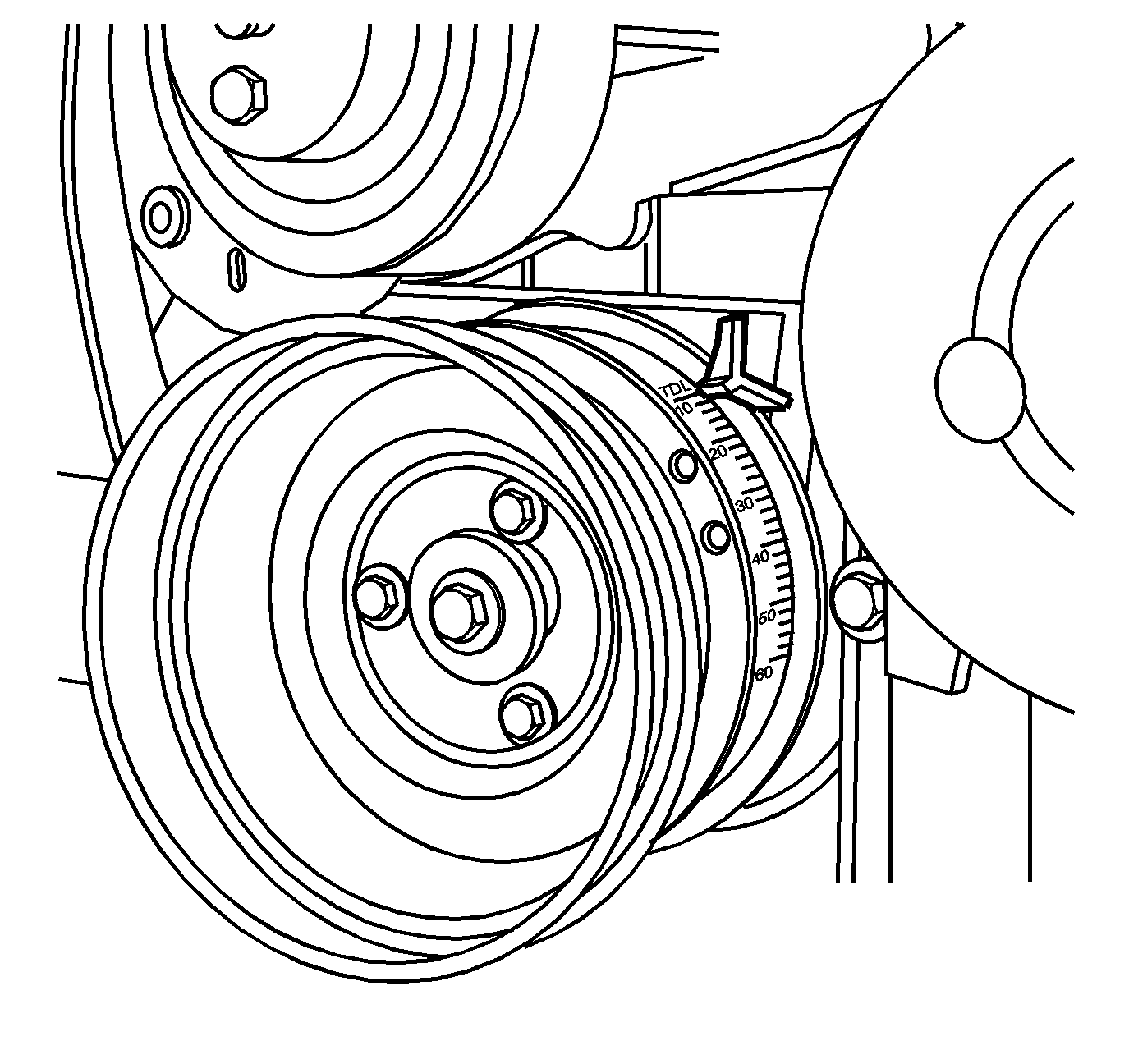
Important: Prior to camshaft sensor removal and/or to check the camshaft sensor position, align the timing mark on the front engine cover and the crankshaft balancer to 0 degrees top dead center (TDC). Be sure the bank 1 cylinder 1 is on the compression stroke, or that the intake and exhaust valves are closed.
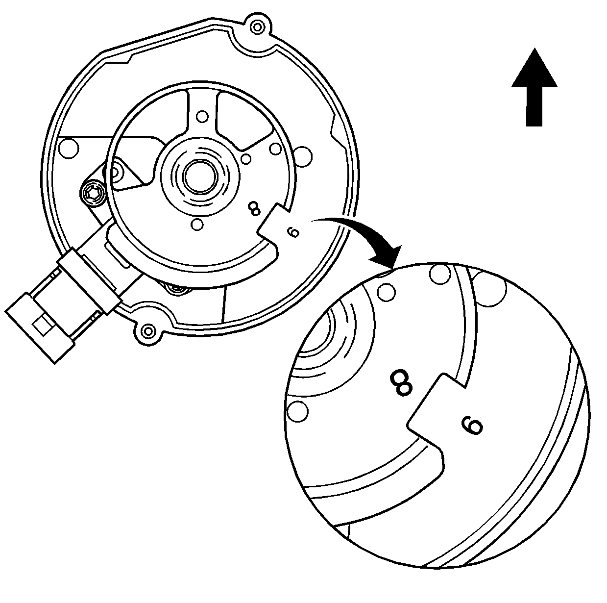
Camshaft Position Sensor Replacement
- Disconnect the negative battery cable.
- Remove the interior engine access cover if applicable.
- Disconnect the electrical connector from the camshaft position sensor.
- Remove the camshaft position sensor retaining bolt.
- Remove the camshaft position sensor.

Important: Prior to camshaft sensor removal, align the timing mark on the front engine cover and the crankshaft balancer to 0 degrees top dead center (TDC). Be sure the bank 1 cylinder 1 is on the compression stroke, or that the intake and exhaust valves are closed.
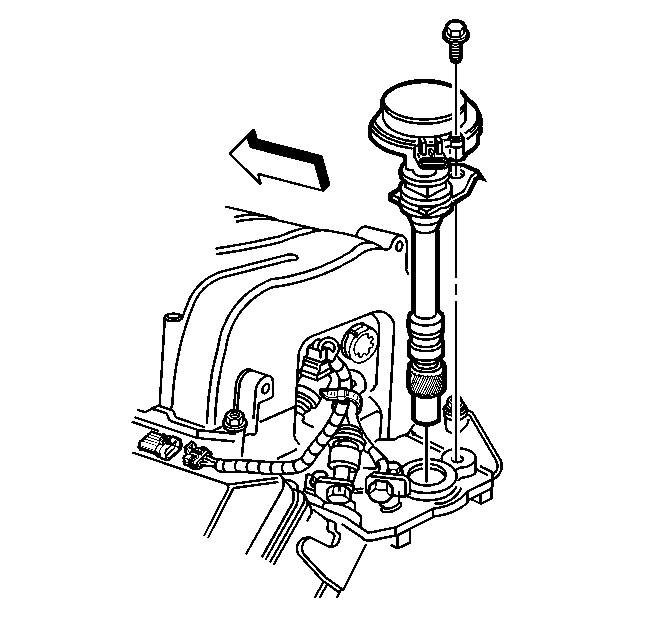
Installation Procedure
- Align the spot mark on the camshaft position sensor gear with the paint mark on the camshaft position sensor lower base.
- Remove the cover from the camshaft position sensor.
- Use a long flat blade screwdriver to rotate the oil pump driveshaft to engage the tang of the camshaft position sensor drive gear.
- Without holding the reluctor wheel, guide the camshaft position sensor into the hole in the intake manifold until the camshaft position sensor is seated. The reluctor wheel will turn clockwise as the camshaft position sensor is lowered into the engine.
- When properly installed, the reluctor wheel cutout should be in approximately the four o'clock position and should line up with the stamped number "9" on the camshaft position sensor housing.
- Install the camshaft position sensor hold down clamp and bolt.
- Install the camshaft position sensor cover and screws. Do not over tighten.
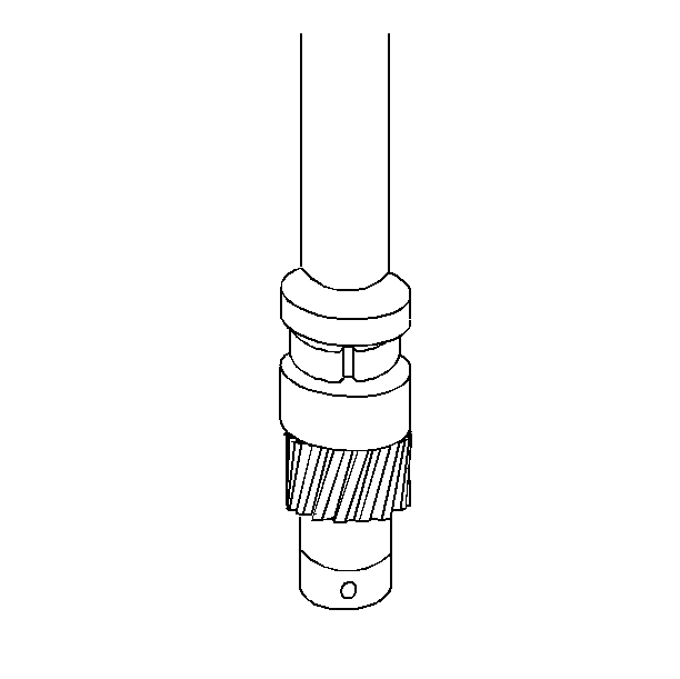
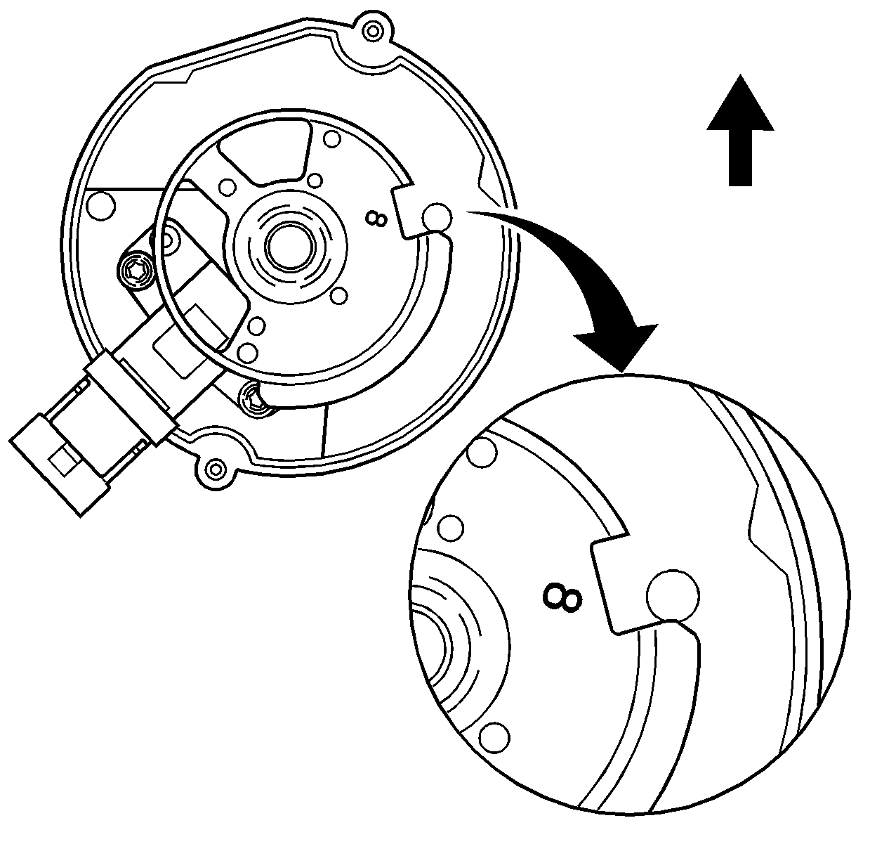
Important: This alignment is prior to installation with the shaft in proper alignment but not in the final installed position.


Important: Refer to Fastener Notice in Cautions and Notices.
Important: The camshaft position sensor hold down clamp must properly align with the mounting hole in the intake manifold. Repeat the installation procedure if the proper alignment is not obtained.
Tighten
Tighten the bolt to 33 N·m (24 lb ft).
Tighten
Tighten the screws to 5 N·m (40 lb in).
Warranty Information
For vehicles repaired under warranty, use:
Labor Operation | Description | Labor Time |
|---|---|---|
J4350 | SENSOR, CAMSHAFT POSITION - REPLACE | Used published labor time |
