REVISED AIR COMPRESSOR MOUNTING BRKT./BELT ADJUSTER

SUBJECT: REVISED AIR COMPRESSOR MOUNTING BRACKET ASSEMBLY
MODELS: 1980-87 MEDIUM DUTY C6/7, B6 AND P6 EQUIPPED WITH 8.2L DIESEL ENGINE (LH3/LH4) AND AIR BRAKES WITH TWO PIECE AIR COMPRESSOR BRACKETS.
Effective January 1987, a revised air compressor support bracket was released in production on the 8.2L diesel engine. This revised bracket incorporates several new parts, including a separate air compressor belt adjuster and a one piece air compressor support. This product change improved ability to adjust the air compressor belt without loosening bracket attachment fasteners.
Listed below are the removal and installation instructions for vehicles manufactured prior to January, 1987, for the MIDLAND - AIR COOLED (RPO K55), MIDLAND - WATER COOLED (RPO K56) and BENDIX - WATER COOLED (KYA) Air Compressors.
1. MIDLAND AIR COOLED COMPRESSOR (K55)
Removal of Existing Parts
o Block vehicle wheels.
o Disconnect negative battery cable.
o Exhaust the compressed air from the air system. Drain all reservoirs.
o Disconnect the air and oil lines from the compressor.
o Remove and discard the drive belt from the compressor.
o Remove the air compressor and mounting bracket assembly from the engine.
o Remove and discard the belt tensioner assembly and mounting bracket.
o Remove and discard all remaining brackets used with this compressor.
o Remove and discard oil lines. Replace engine fittings and clamps as required.
o Separate compressor from mounting bracket and discard bracket.
o Remove and discard pulley from compressor along with the jam lock nut.
o Remove lower base mounting bracket from air compressor and discard.
o Scrap air compressor mounting gasket.
Installation of New Parts
Perform the steps below on a shop bench.
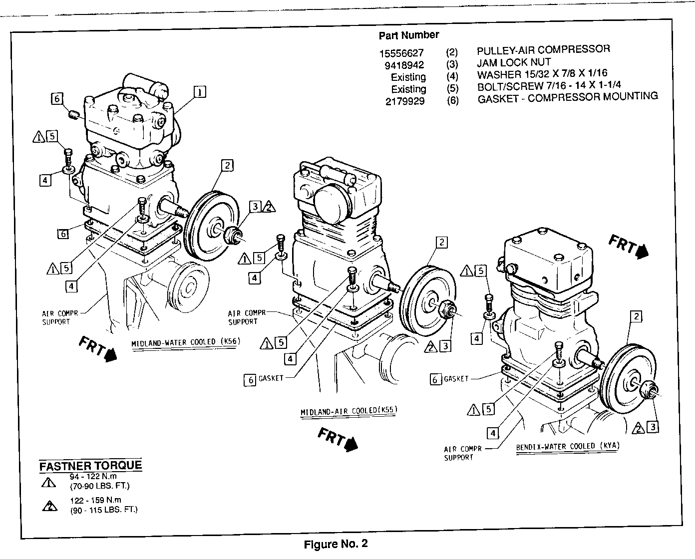
o Install new pulley [2] on the air compressor. Torque jam lock nut [3] (Figure No. 2).
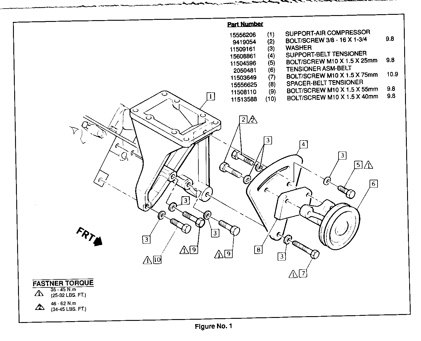
o Subassemble spacer [8], belt tensioner support [4] and belt tensioner Assembly [6]. Torque bolts (Figure No. 1).
IMPORTANT: When working on a truck with tilt hood, install air compressor and support bracket as an assembly. If work is performed on a truck with a conventional hood, install support bracket on engine first and then install compressor.
o After air compressor mount is installed, insert a .020 feeler gage and check for clearance between bracket and intake manifold. If fouling occurs, refer to Bulletin 88-T-71.
o Install air compressor to its mounting support using new gasket. Torque bolts [5] (Figure No. 2).
o Install belt tensioner assembly to the compressor mounting bracket with bolt [7] (Figure No. 1).
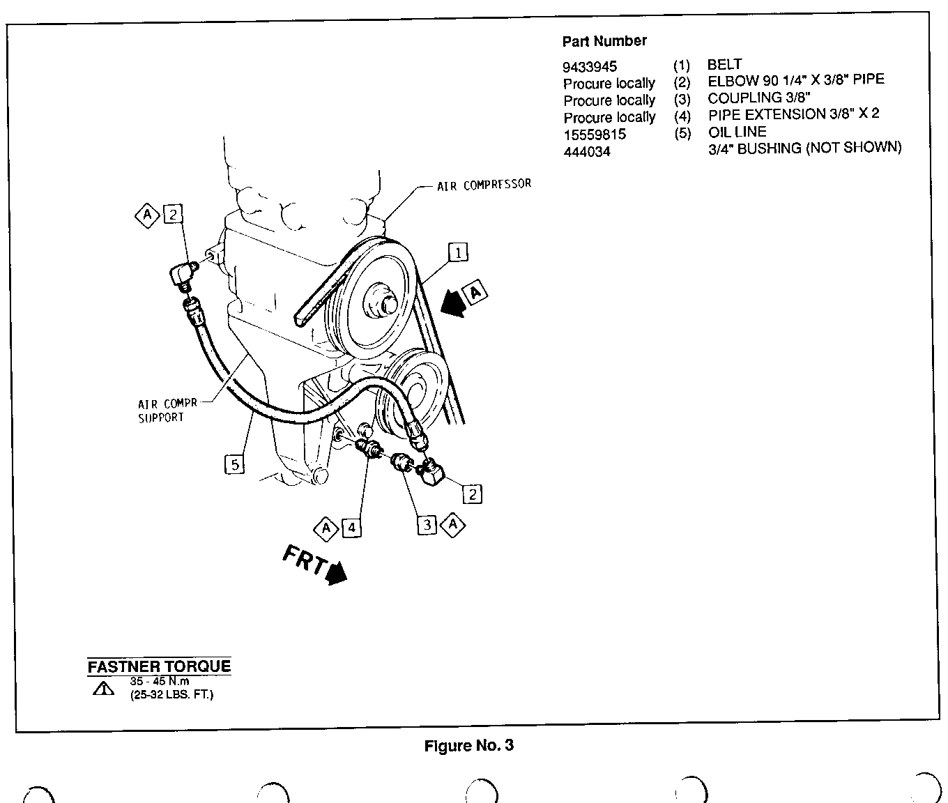
o Install existing oil drain fitting to new 3/4 inch bushing and install on support bracket. Seal using Loctite pipe sealant or equivalent (Figure No. 3).
o Reconnect oil and air lines to air compressor.
o Install drive belt [1], adjust belt tensioner to (120-140 lbs.) and Torque bolt [5] and [7] (Figure No. 1).
o Check engine oil level and fill if required.
o Reconnect negative battery cable.
o Recharge air system to 120 P.S.I.
IMPORTANT: After completing the above steps check for air/oil leaks and proper brake operation.
For repairs performed under warranty, use:
Labor 0p: T7605 Time: 1.4 hrs Add. 3 hr for installation on truck with a standard steel hood.
2. MIDLAND WATER COOLED COMPRESSOR (K56) BENDIX WATER COOLED COMPRESSOR (KYA)
Removal Of Existing Parts
o Block vehicle wheels.
o Disconnect negative battery cable.
o Exhaust the compressed air from the air system. Drain all reservoirs.
o Drain the cooling system below the level of the air compressor coolant lines.
o Disconnect air, oil, and water lines from the compressor.
o Remove and discard the drive belt from the compressor.
o Remove the air compressor and mounting bracket assembly from the engine. Discard the bracket.
o Remove and discard the belt tensioner assembly and mounting bracket.
o Remove and discard remaining mounting brackets from engine and the adjuster arm bracket.
o Separate and discard pulley and jam nut from the compressor.
o Remove lower base mounting bracket from air compressor and discard.
o Scrap air compressor mounting gasket.
Installation of New Parts
Perform the steps below on shop bench.
o Install new pulley [2], Jam locknut, and cotter pin. Torque jam nut (Figure No. 2).
o Subassemble spacer [8], belt tensioner support [4], and belt tensioner assembly [6]. Torque bolts (Figure No. 1).
o Install oil feed extension, coupler and 90 degree elbow on cylinder head (Figure No. 3)
IMPORTANT: When working on a truck with a tilt hood, install air compressor and support bracket as an assembly. If work is performed on a truck with standard steel hood, install support bracket on engine first and then install compressor.
o After air compressor mount is installed, insert a .020 feeler gage and check for clearance between bracket and intake manifold. If fouling occurs refer to bulletin #88-T-71.
o Install belt tensioner assembly to the compressor mounting bracket with bolt [7] (Figure No. 1).
o Install air compressor to its mounting support using new gasket. Torque bolts [5] (Figure No. 2).
o Install 3/4 inch bushing on air compressor support and attach existing oil drain fitting. Seal using Loctite pipe sealant or equivalent.
o Install new oil feed line between cylinder head and air compressor (Figure No. 3).
o Reconnect water and air lines to air compressor.
o Install drive belt [1] (Figure No. 3). Adjust belt tensioner to (120-140 lbs) and torque bolts [5] and [7] (Figure No. 1).
o Refill radiator with coolant.
o Check engine oil level and fill if required.
o Reconnect negative battery cable.
o Recharge air system to 120 P.S.I.
IMPORTANT: After completing the above steps check air brakes for air/water/oil leaks and proper brake operation.
For repairs performed under warranty, use:
Labor 0p: T7610 Time: 2.7 hrs Add .3 hr for installation on trucks with a standard steel hood.
PARTS INFORMATION
New parts which must be installed to perform this modification are listed below:
QUANTITY PART NUMBER DESCRIPTION -------- ----------- ----------- 1 15556206 Support - Air Compressor 7 11509161 Washer 1 15608861 Support - Belt Tensioner 1 2050481 Tensioner Asm - Belt 1 15556625 Spacer - Belt Tensioner 1 15556627 Pulley - Air Compressor 1 9418942 Jam Lock Nut 1 9433945 Belt 1 2179929 Gasket - Compressor Mounting 1 15559815 Off Line 1 444034 3/4" Bushing 2 11508110 Bolt/Screw M10X1.5X55mm 9.8 Grade 1 11513588 Bolt/Screw M10X1.5X40mm 9.8 Grade 1 11504596 Bolt/Screw M10X1.5X25mm 9.8 Grade 2 9419054 Bolt/Screw 3/8"-16X1 3/4" 9.8 Grade 1 11503649 Bolt/Screw M10X1.5X75mm 10.9 Grade 2 Procure Locally Elbow 90 Degree 1/4"X3/8" Pipe 1 Procure Locally Coupling 3/8" 1 Procure Locally Pipe Extension 3/8"X2"
Parts are currently available from GMSPO.


General Motors bulletins are intended for use by professional technicians, not a "do-it-yourselfer". They are written to inform those technicians of conditions that may occur on some vehicles, or to provide information that could assist in the proper service of a vehicle. Properly trained technicians have the equipment, tools, safety instructions and know-how to do a job properly and safely. If a condition is described, do not assume that the bulletin applies to your vehicle, or that your vehicle will have that condition. See a General Motors dealer servicing your brand of General Motors vehicle for information on whether your vehicle may benefit from the information.
