PRE-MATURE FRONT TIRE WEAR (REPLACE STEERING LINKAGE)

SUBJECT: FRONT TIRE WEAR, REVISED ACKERMAN ANGLE
MODELS: 1983-89 CO, C7, B6, P6 VEHICLES WITH 189" OR LONGER WHEELBASE
Some long wheelbase vehicles equipped with a 7,000 lb, 7,500 lb, or 9,000 lb rated capacity front axle making frequent turns may experience front tire wear or outer edge scuffing. To eliminate this condition, new steering linkages are available which will optimize the steering geometry providing increased front tire life.
Vehicles manufactured after the following Vehicle Identification Numbers are equipped with the new steering linkage:
GMC KV518781 Chevrolet KV112745
Detailed instructions for the removal and installation of all steering components are covered in the 1988 Medium Duty Service Manual, X-8833, Sec- tion 3B.
This bulletin applies to several vehicle models, front axle and wheel/tire option combinations. After determining the model and option content of the vehicle, select the appropriate procedure from those listed below:
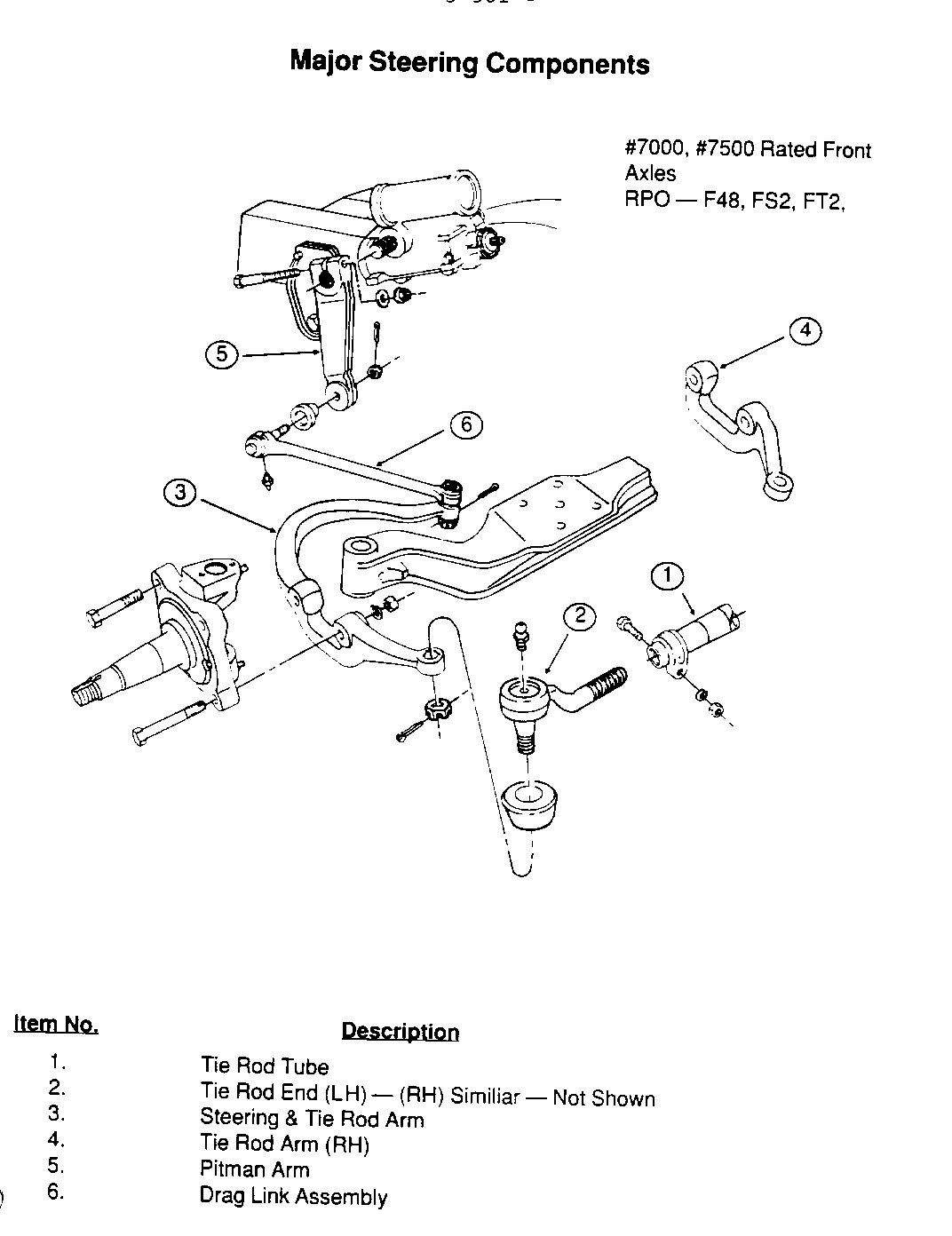
C/P/B Models with 7,000/7,500 lb Front Axle
For vehicles equipped with 7,000 lb rated front axles (RPO F48, FS2, FT2) or 7,500 lb rated front axles (RPO FRD, FRW) use the following procedure:
IMPORTANT: If vehicle is equipped with the following optional front wheels, disregard use of this bulletin.
20 X 7.5 (RPO QH1, QK8) 20 X 7.0 (RPO RCE)
Service Procedure:
1. Set parking brake.
2. Block vehicle rear wheels.
3. Using steering linkage puller, J-26813-B, remove the tie rod tube and ends from tie rod arm and steering arm.
4. Using puller J-26813-B, remove drag link from pitman arm and steering arm.
5. Remove pitman arm from pitman shaft using puller J-26813-B.
6. Remove RH tie rod arm from knuckle.
7. Remove the steering and tie rod arm.
8. Position and install new steering and tie rod arm to LH knuckle. Torque bolts between 300-375 lbs/ft (406-508 Nm).
9. Install new tie rod arm onto RH knuckle. Torque bolts between 300-375 lbs/ft (406-508 Nm).
10. Install new tie rod tube and new tie rod ends into steering arm and tie rod arm. Note that new tie rod ends must be installed into top of steering arm and tie rod arm.
11. Torque nuts securing tie rod end ball studs to steering arm and tie rod arm between 148-180 lbs/ft (200-244 Nm).
12. Position and install new pitman arm and drag link to steering arm and pitman shaft. Torque pitman arm clinch bolt between 100-130 lbs/ft (149-176 Nm) and ball stud nuts between 89-111 lbs/ft) (120-150 Nm).
13. Lubricate all steering linkage grease fittings with lubricant (GM P/N 1052497) or equivalent.
14. Align front end to specifications listed in Section 3A in the 1988 Medium Duty Service Manual X-8833. Wheel stops must be reset to allow a minimum 5/8" (16 mm) clearance between in- side of tire and frame rail.
15. Unblock rear wheels.
16. Release parking brake.
17. Road test vehicle.
The following parts are required to perform this procedure:
Description Part Number Quantity ----------- ----------- -------- Tie Rod Tube (w/clamps) 15616293 1 Tie Rod Assembly (LH) 15622068 1 Tie Rod Assembly (RH) 15622069 1 Steering and Tie Rod Arm 15622180 1 Tie Rod Arm (RH) 15622181 1 Pitman Arm 15622065 1 Drag Link Assembly 15622066 1 Lubricant 1052497 A/R
Part number 15622065 is currently available from GMSPO. AU other parts listed above are expected to be available on August 8, 1989. Until then normal part orders win not be accepted by GMSPO. Only verifiable emergency VIP orders will be accepted. SPO win make every effort to obtain parts. All parts will be placed on 400 control to waive VIP surcharges. However, the parts will be shipped premium at dealer's expense. All other order types will be canceled as incorrectly ordered while the 400 control is in place.
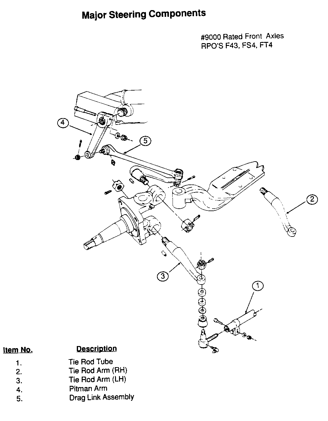
C/P/B Models with 9,000 Lb Front Axle ------------------------------------- For vehicles equipped with a 9000 lb rated capacity front axle (RPO F43, FS4, F74) use the following procedure.
IMPORTANT: If vehicle is equipped with the following optional front wheels, disregard use of this bulletin:
20 X 8.0 (RPO QJ3) 20 X 7.5 (RPO QK7) 22.5 X 8.25 (RPO QM6, RRS)
Procedure
1. Set parking brake.
2. Block the vehicle rear wheels.
3. Using steering linkage puller J-26813-B, remove the tie rod tube and ends from tie rod arms. Check the tie rod ends for looseness. If OK, loosen tube clamps and unscrew. Remove and save ends for reuse.
4. Loosen and remove LH and RH tie rod arms from knuckles.
5. Disconnect and remove pitman arm from drag link and pitman shaft using puller J-26813-B.
6. Remove drag link from steering arm using puller J-26813-B.
7. Position and install new tie rod arms into knuckles. Torque nuts to 413 lb/ft (560 Nm).
8. Install new tie rod tube and ends into tie rod arms. Torque nuts securing ball studs to arms between 125 - 148 lb/ft (170 - 205 Nm).
9. Position and install new pitman arm and drag link to steering arm and pitman shaft.
10. Torque pitman arm clinch bolt between 110 - 130 lb/ft (149 - 176 Nm) and ball stud nuts between 125 - 151 lb/ft (170 - 205 Nm).
11. Lubricate all steering linkage grease fittings with lubricant (GM P/N 1052497 or equivalent).
12. Align front end to specifications listed in Section 3A in the 1988 Medium Duty Service Manual X-8833. Check wheel stops and reset if necessary to allow a minimum of 5/8" (16mm) clearance between inside of tire and frame rail. Torque tie rod clamp bolts between 39 - 55 lb/ft (54 - 75 Nm).
13. Unblock rear wheels.
14. Release parking brake.
15. Road test vehicle.
Parts Information
The following parts are required to perform this procedure:
Description Part Number Quantity ----------- ----------- -------- Tie Rod Tube (w/clamps) 15618114 1
Tie Rod Arm (RH) 15622063 1
Tie Rod Arm (LH) 15622064 1
Pitman Arm 15625712 1
Drag Link Assembly 15625713 1
Lubricant 1052497 A/R
Parts required to make this modification win be offered at an attractive dealer cost through December 1, 1989. Parts ordered after December 1, 1989 will be subject to revised price schedules.
Part number 15625713 is expected to be available on September 8, 1989. Until then normal part orders will not be accepted by GMSPO. Only verifiable emergency VIP orders will be accepted. SPO will make every effort to obtain parts. All parts will be placed on 400 control to waive surcharges. However, the part will be shipped premium transportation at dealer's expense. All other order types will be canceled as incorrectly ordered while the 400 control is in place.
All other parts listed directly above are currently available from GMPSO.


General Motors bulletins are intended for use by professional technicians, not a "do-it-yourselfer". They are written to inform those technicians of conditions that may occur on some vehicles, or to provide information that could assist in the proper service of a vehicle. Properly trained technicians have the equipment, tools, safety instructions and know-how to do a job properly and safely. If a condition is described, do not assume that the bulletin applies to your vehicle, or that your vehicle will have that condition. See a General Motors dealer servicing your brand of General Motors vehicle for information on whether your vehicle may benefit from the information.
