REDUCED DRIVEABILITY WHEN COLD (INSTALL NEW SERVICE KIT)

SUBJECT: REDUCED DRIVEABILITY DURING COLD OPERATION (INSTALL SERVICE KITS)
VEHICLES AFFECTED: 1985-88 MEDIUM DUTY TRUCKS WITH W/5.7L, 6.0L, AND 7.0L AND U.S. FEDERAL EMISSIONS (R.P.O.NA5)
Some 1985-88 Medium Duty trucks equipped with 5.7L, 6.0L, or 7.0L may exhibit the two following conditions during cold engine startup and vehicle operation.
1. Afterfires during engine deceleration or engine shutdowns.
2. Long crank times to start.
3. Hesitation/stumbles after startup and before full operating temperatures are obtained.
These three conditions were corrected in production June 6, 1988 effective with these vehicles:
GMC - 1GDL7D1B5JV530108 Chevrolet - 1GBL7D1B5JV116299
If these conditions are encountered on vehicles built before these VIN breakpoints they can be improved by installing two service kits. Listed below is description and installation procedure for each of these kits.
Kit "A"- Carburetor This kit will improve engine startability and driveability during engine operation. This kit contains carburetor parts to modify:
1. Choke lever
2. Choke spring (stiffer)
3. Fast idle cam
4. Accelerator pump nozzle - (increased from .025 to .032)
Kit "B"- Electrical This kit will prevent exhaust system "popping or afterfire". This service kit provides a switch which is wired in series with the diverter valve on the A.I.R. system and is attached to the air cleaner housing. The purpose of this switch (sensor) is to prevent the A.I.R. system from functioning (pumping air to exhaust manifold) until air cleaner incoming inlet air reaches 60 degrees F. (160 C).
This switch is normally open below 60 degrees F (16C). Above 60 degrees F (16C) the switch should close allowing normal operation of the A.I.R. management system.
Service Procedure For Kit "A" - (Holley Carburetor only)
IMPORTANT: Kit "A" only applies to 6.OL/7.OL - carburetor modifications will not be made on 5.7L engine.
1. Remove air cleaner element and canister.
2. Remove carburetor.
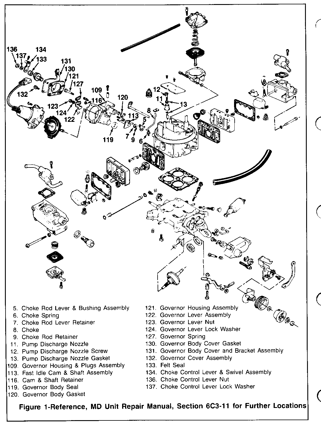
3. Remove governor cover and bracket assembly (131) from governor housing by removing the choke control lever (134), nut (136), lockwasher (137), felt seal (133), gasket and four screws (132). Remove governor spring (127) (Figure No. 1).
4. Remove nut (123) and lockwasher (124) that retains the governor lever (122) onto the end of the throttle plate shaft. Separate the governor lever from the throttle plate shaft (Figure No. 1).
5. Remove governor housing (109) from the carburetor main body, by removing three screws (121), gasket (120) and shaft seal (119) (Figure No. 1).
IMPORTANT: Care should be given to the back side of governor housing as the detent ball may fall out of location. (May be necessary to hold in location.)
6. Remove "C" clip (116) from fast idle cam and shaft assembly (113). Remove fast idle cam and shaft assembly. Install new fast idle cam (113) and shaft assembly and "C" clip (116) (Figure No. 1).
IMPORTANT: Partially open throttle to allow roll pin to clear fast idle pin.
7. Remove choke lever (5) and choke closure spring (6) from carburetor main body. This requires removing the "E" clip from the choke lever shaft (7) and the "R" clip (9) from the choke rod (8) (Figure No.1).
8. Install new choke closure spring (6) on top of new choke lever (5) onto carburetor main body. Install new "E" clip (7) (Figure No. 1).
9. Reinstall governor housing (109) onto carburetor main body using new shaft seal (119) and gasket (120). Make sure there is no gasket residue on main body or governor housing surfaces. Torque the three screws (121) to 50 in./lbs. (Figure No. 1).
10. Reinstall governor lever (122), lockwasher (124) and nut (123) on to end of throttle plate shaft. The flats inside the lever must be aligned over the flats on throttle plate shaft. Torque the nut to 30 in. lbs. Reinstall governor spring (Figure No. 1).
11. Reinstall governor cover (131) and bracket assembly and gasket (130) onto the governor housing. Make sure there is no gasket residue on the housing or plate. Torque the four screws to 18 in. lbs. (Figure No. 1).
12. Reinstall the felt seal (133), choke control lever (134), lockwasher (137) and nut (136) onto the shaft. The flats on the inside of the lever must be aligned over the flats on the shaft. Torque the nut to 18 in. lbs. (Figure No 1).
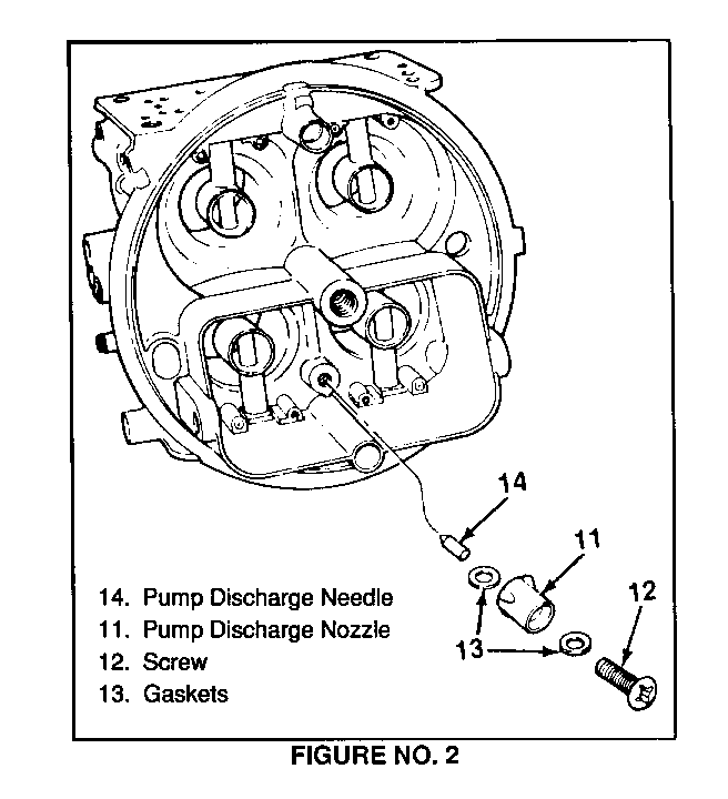
13. Remove accelerator pump discharge nozzle screw (12), nozzle (11), and gaskets (13) and install new nozzle (12) with gaskets (13) (Figure No 2).
14. Install carburetor on truck. (Torque to 20-24 ft. lbs.)
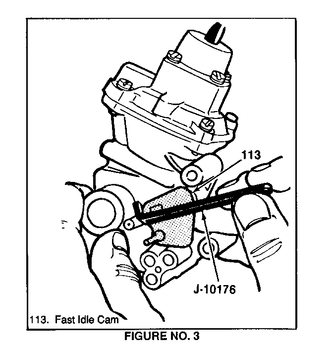
15. Start vehicle, set fast idle at 2600 RPM using idle tool included in kit (Figure No. 3)
After completing carburetor revisions proceed to A.I.R. system modifications cold override Kit "B".
Service Procedure - Cold Override Kit "B" (5.7L, 6.0L, 7.0L) with NA5 Federal Emissions
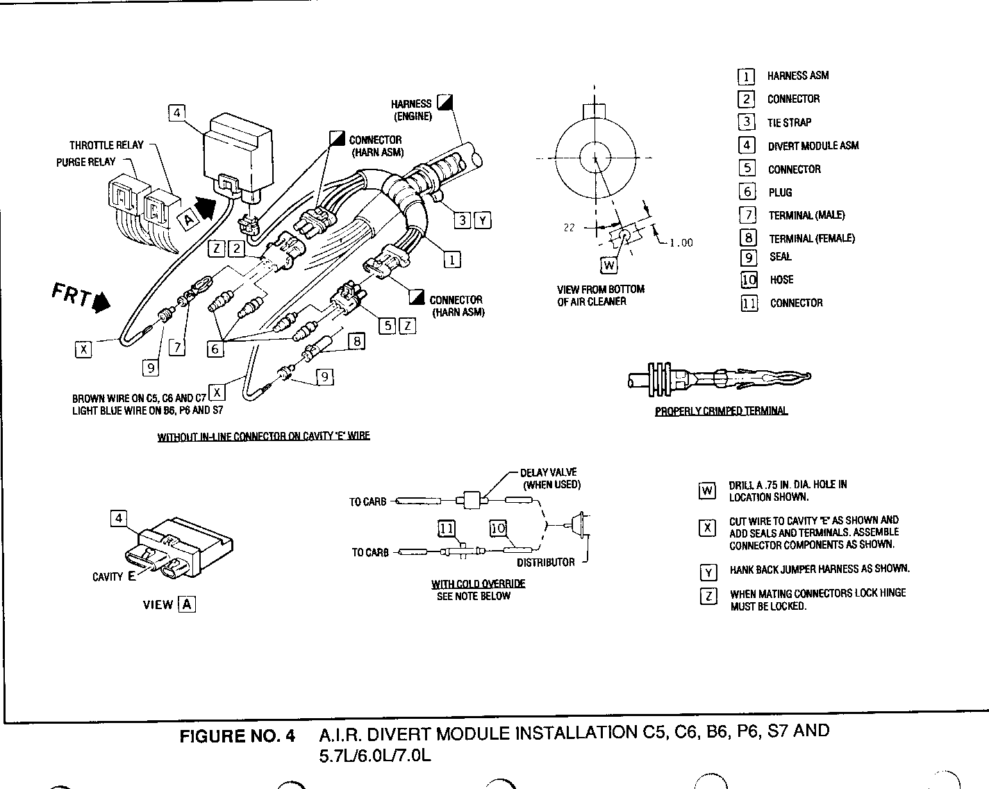
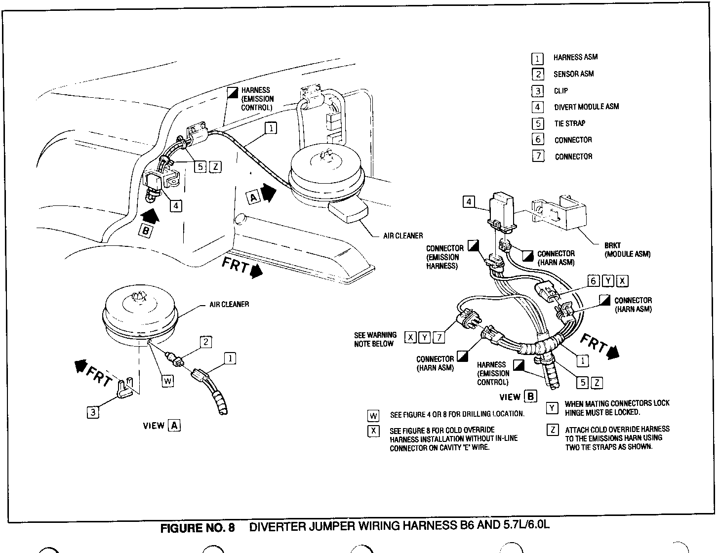
1. With air cleaner canister removed, drill a 3/4-inch diameter hole, 160-180 degrees from air cleaner inlet opening (shown on Figure No. 4 and Figure No. 8).
IMPORTANT: Before drilling hole, make sure no other component will hit sensor once installed in air cleaner.
After locating 160-180 degrees from inlet opening, measure from top of air cleaner base 1-inch down and centre punch before drilling 3/4-inch hole. Also be sure all metal shavings are completely cleaned out of air cleaner base.
2. Install temperature sensor (2) in hole and secure with retainer clip (3).
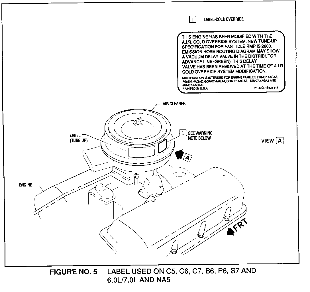
3. Check tune-up label on vehicle to determine if the vehicle has a delay valve in the vacuum advance hose line. (Figure No. 5) If delay valve is present, remove and discard the valve. Insert hose (10) and connector (11) (Figure No. 4) in place of valve. Also, check condition of hose. If hose is damaged or deteriorated, replace it with new hose.
4. Reinstall air cleaner base, element, and cover.
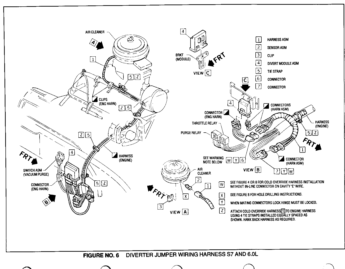
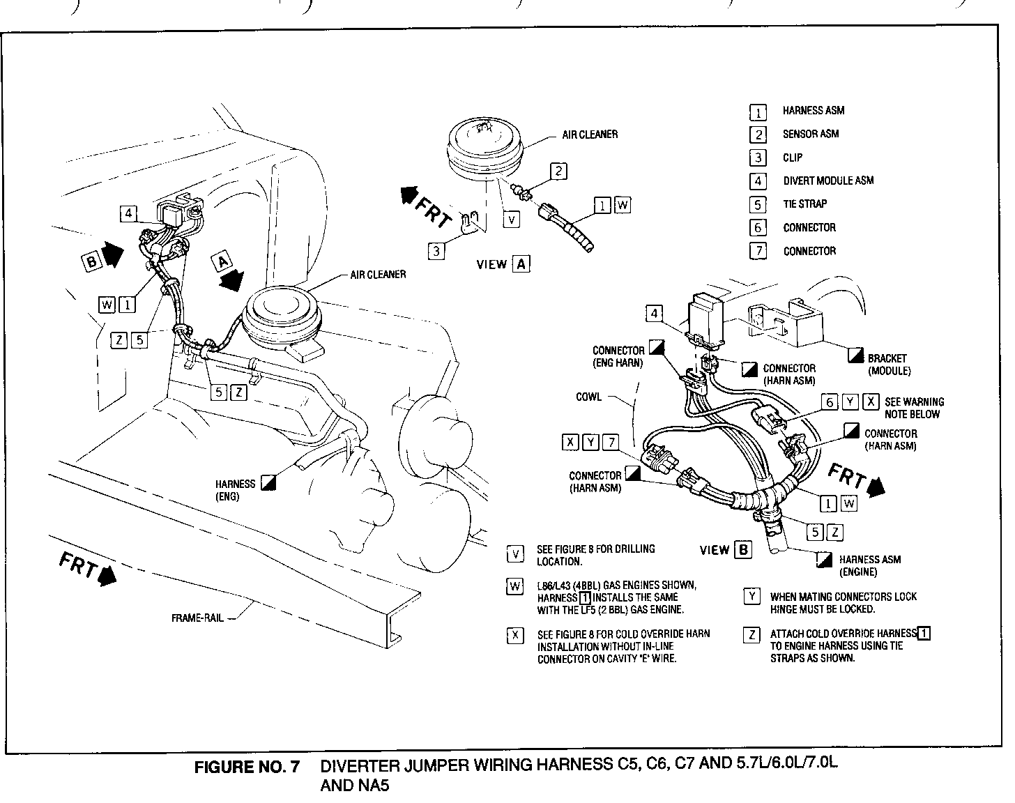
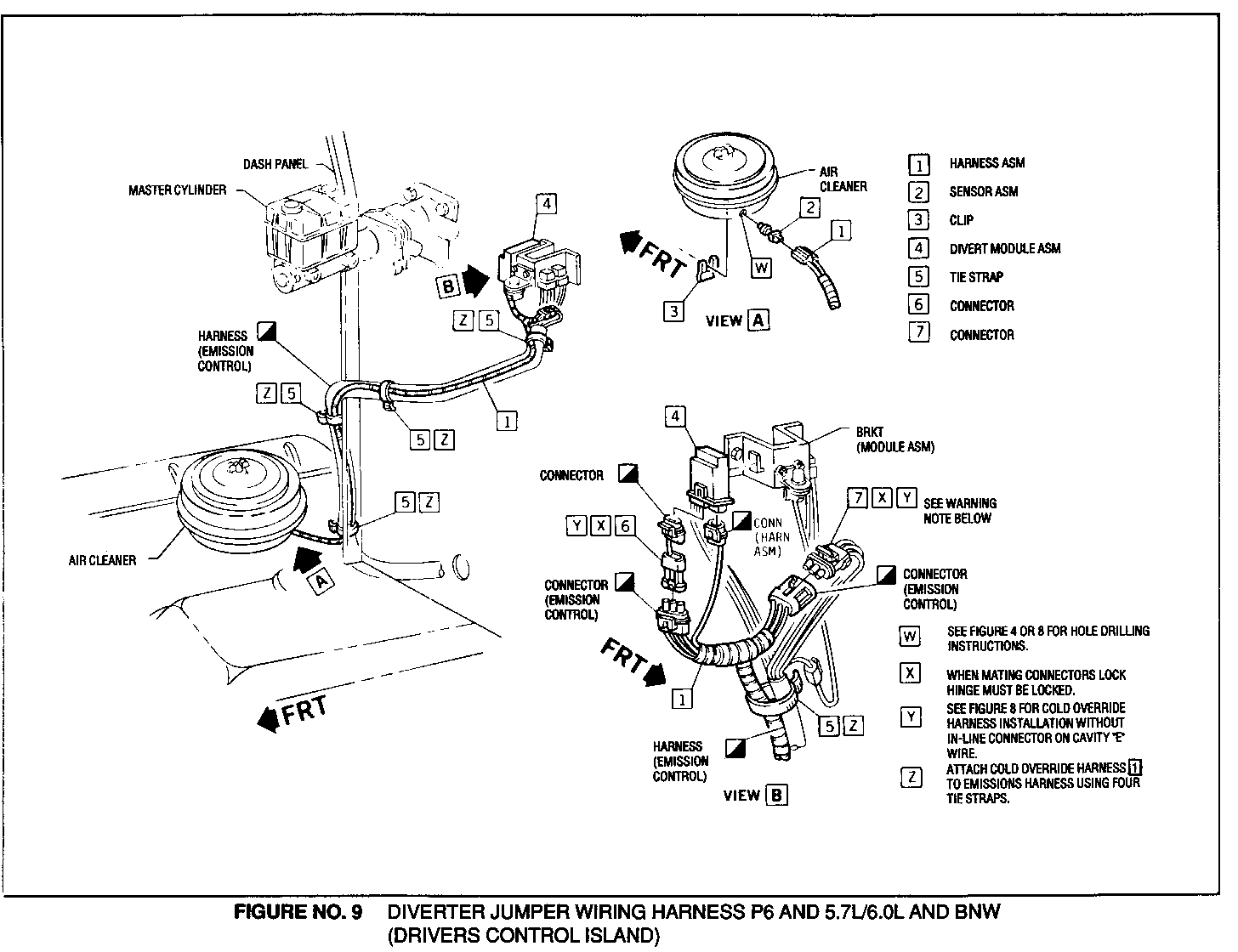
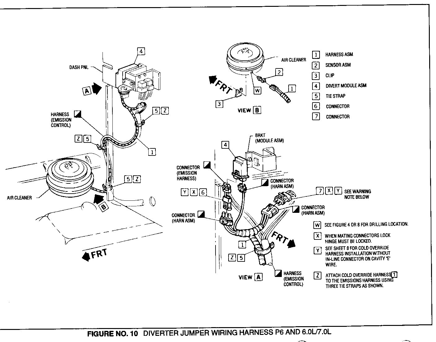
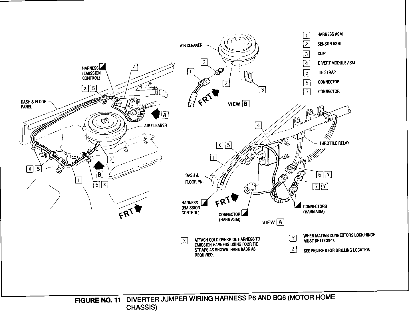
5. Unplug harness connector to diverter module (Figure 6 through 11). The type of truck and engine combination will determine which figures are used for the following steps:
C5,C6,C7,S7, and P6 Motor Home Chassis Models - The diverter module connects directly to the engine harness.
B6 and P6 Non-Motorhome Chassis Models - The diverter module connects to the emission control module.
6. Remove old diverter module from mounting bracket and discard.
7. Install new diverter module (4) from kit.
8. If existing engine harness or emission control harness does not have a three-way in-line connector on the diverter connector "E" cavity wire (light blue on B6, P6, and S7 and brown on C5,C6 and C7), a connector must be added (Figure No 4).
IMPORTANT: If three-way connector is present, proceed to Step 11.
9. Cut wire to cavity "E" and strip back insulation 1/4 inch. Install new three-way weather pack connector as follows (Figure 4):
A. Install seals (9) on both ends of cut wire.
B. Install male terminal (7) on wire to module (4) and female terminal (8) to wire on engine or emissions harness.
C. Install male terminal (7) into "A" cavity of female harness.
D. Install plugs (6) into unused "B" and "C" cavities of both connectors.
E. Close and lock connector hinge locks.
10. Install the three-way connectors on the diverter module jumper harness (1) between the two halves of the (added in step 9) three-way connectors on the cavity "E" wires.
11. Plug two-way metri pack connector on jumper harness (1) into the diverter module two-way receptacle.
12. Route other end of the jumper harness (1) with the engine harness or the emission control harness to the air cleaner and plug two-way connector into temperature sensor (2) (Figures 6 through 11).
13. Tie wrap jumper harness (1) to engine harness or emission control harness with the 8 tie-straps (5) from the kit (Figures 6 through 11).
14. Install cold over-ride label (1). See Figure No. 5 for air cleaner label location.
IMPORTANT: Area must be clean and dry before installing label.
Test Procedure For Kit "B".
A. Turn on ignition, the "Check Engine" light should come on. Light will remain on one to two seconds.
B. Disconnect both connectors at air divert solenoids. "Check Engine" Light should be on and remain on during test.
C. Start engine and idle. Air should be diverted to air cleaner. May take 20 to 25 seconds before air diverts to air cleaner.
D. Reconnect diverter connector. Air should be diverted to exhaust ports.
IMPORTANT: There is a 20 to 25 second time delay at idle for solenoids to re-energize and divert air to exhaust. Additionally, air temperature in cleaner must be 60+3.5 degrees F (15.5+2.0 degrees C) for air to divert to exhaust.
Parts Information
IMPORTANT: Kit "B" is only used on 5.7L engine. The 6.0/7.0 engine uses both service kits. Listed below each kit is the quantity and part name of those parts included in Kit "A" and "B so.
ONLY THESE TWO PART NUMBERS REQUIRED WHEN ORDERING SERVICE KIT.
Part Number Description Quantity ----------- ----------- -------- 15640682 Service Kit "A" (Carburetor Parts) 1
Kit "A" Includes:
Governor Housing Gasket 1 Pump Discharge Nozzle Gasket 2 Flange Gasket 1 Choke Lever 1 Pump Discharge Nozzle 1 Choke Return Spring 1 Fast Idle CAM ASM 1 Choke Rod Retainer 1 Choke Rod "E" Ring Retainer 1 Fast Idle Wrench 1 Instruction Sheet 1
15639868 Service Kit "B" (Electrical Parts) 1
Kit "B" Includes:
Instruction/Graphic Sheet 1 Label - Cold Override 1 Module - Air Divert 1 Sensor 1 Clip - Sensor Retainer 1 Harness - Cold Override 1 Tie Strap 8 Hose 1 Connector 1 Connector (3F, W/Pack) 1 Connector (3M, W/Pack) 1 Terminal 1 Terminal 1 Cable Seal 2 Seal Plug 4
Parts should be ordered on a V.I.P. or 'E' basis.
General Motors bulletins are intended for use by professional technicians, not a "do-it-yourselfer". They are written to inform those technicians of conditions that may occur on some vehicles, or to provide information that could assist in the proper service of a vehicle. Properly trained technicians have the equipment, tools, safety instructions and know-how to do a job properly and safely. If a condition is described, do not assume that the bulletin applies to your vehicle, or that your vehicle will have that condition. See a General Motors dealer servicing your brand of General Motors vehicle for information on whether your vehicle may benefit from the information.
