INFORMATION ON MANUAL TRANSMISSION ADJUSTMENT PROC.

SUBJECT: INFORMATION ON MANUAL TRANSMISSION ADJUSTMENT PROCEDURE
MODELS: 1986-1993 W4 STRIPPED CHASSIS WITH MANUAL TRANSMISSION
SERVICE INFORMATION
The manual transmission adjustment procedure on the W4 Stripped Chassis (S/C) "Link Rod" type gear control gear selector is different than the standard W4 Cab Chassis. The S/C adjustment is made in two separate steps; adjustment of the select control and adjustment of the shift control.
ADJUSTMENT INSTRUCTIONS
Select Control Adjustment:
1. Set the shift control lever (stick) in the neutral position.
2. Disconnect the final gear control rod from external select lever of the transmission.
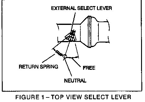
3. Set the external select lever of the transmission to the neutral position (Figure 1 - Top View Select Lever).
NOTE: The lever should be lightly pushed toward the reverse gear direction to remove the play in the neutral position.
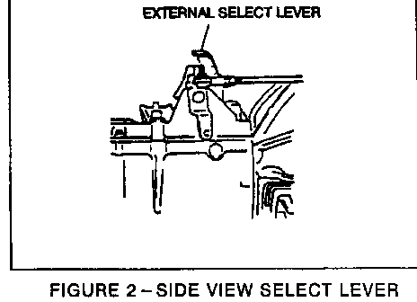
4. Adjust the length of the gear control rod so that it aligns with the center of the external select lever hole and connect the final gear control ball joint to it at this position (Figure 2 - Side View Select Lever).
Measurement
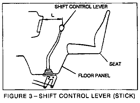
Set the shift control lever (stick) in the neutral position, then measure the dimension between the center of the shift control lever (stick) and the instrument cluster (Figure 3 - Shift Control Lever, stick). The specified length is L = 22.4 inches. If the dimension is different from the specified length, adjust as required.
Shift Control Adjustment
1. Set the shift control lever (stick) so that the distance between the knob center and the instrument cluster is the specified length (L = 22.4 inches) (Figure 3 - Shift Control Lever, stick).
2. Disconnect the final gear control rod from the external shift lever.
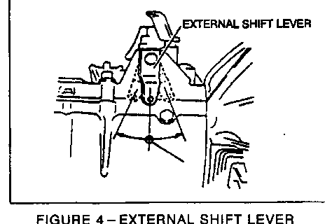
3. Set the external shift lever to the neutral position (Figure 4 - External Shift Lever).
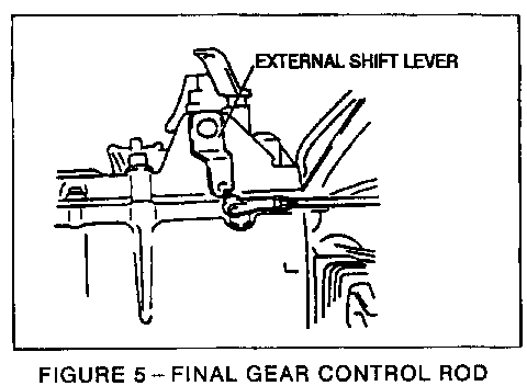
4. Adjust the length of the final gear control rod so that it aligns with the center of the external shift lever hole and connect the gear control rod ball joint at that position (Figure 5 - Final Gear Control Rod).
General Motors bulletins are intended for use by professional technicians, not a "do-it-yourselfer". They are written to inform those technicians of conditions that may occur on some vehicles, or to provide information that could assist in the proper service of a vehicle. Properly trained technicians have the equipment, tools, safety instructions and know-how to do a job properly and safely. If a condition is described, do not assume that the bulletin applies to your vehicle, or that your vehicle will have that condition. See a General Motors dealer servicing your brand of General Motors vehicle for information on whether your vehicle may benefit from the information.
