SERVICE MANUAL UPDATE SEC. 7A REVISED PROCEDURES A/T REPAIRS

SUBJECT: 1989-90 W4 AUTOMATIC TRANSMISSION SERVICE MANUAL REVISION
MODELS: 1988,1989,1990 W4, FL (FLATLOW) AND SC (STRIPPED CHASSIS/WALK-IN)
SERVICE INFORMATION:
This Bulletin revises service manual information in the following sections in the 1990 W4 Automatic Transmission Service Manual:
CONSTRUCTION AND FUNCTION: Pages 7A-18, 7A-20, 7A-23, and 7A-50.
DIAGNOSIS: Pages 7Al -31, 7Al -32 and 7Al -37.
ON-VEHICLE SERVICE: Pages 7A2-10 and 7A2-12.
OVERHAUL: Pages 7A4-30, 7A4-89, 7A4-90 and 7A4-91.
Place the attached information in the appropriate sections of the W4 Automatic Transmission Service Manual.
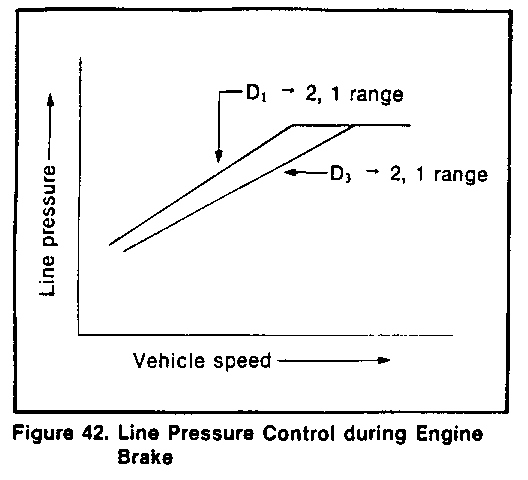
Line pressure control during engine braking by gear selection (Figure 42)
A large driving force is applied to the clutch inside the transmission when down-shifting from D4 or D3 to range 2 or 1, and the desired engine braking effects are not obtainable. Therefore, the line pressure parameters for engine brake are set higher than normal.
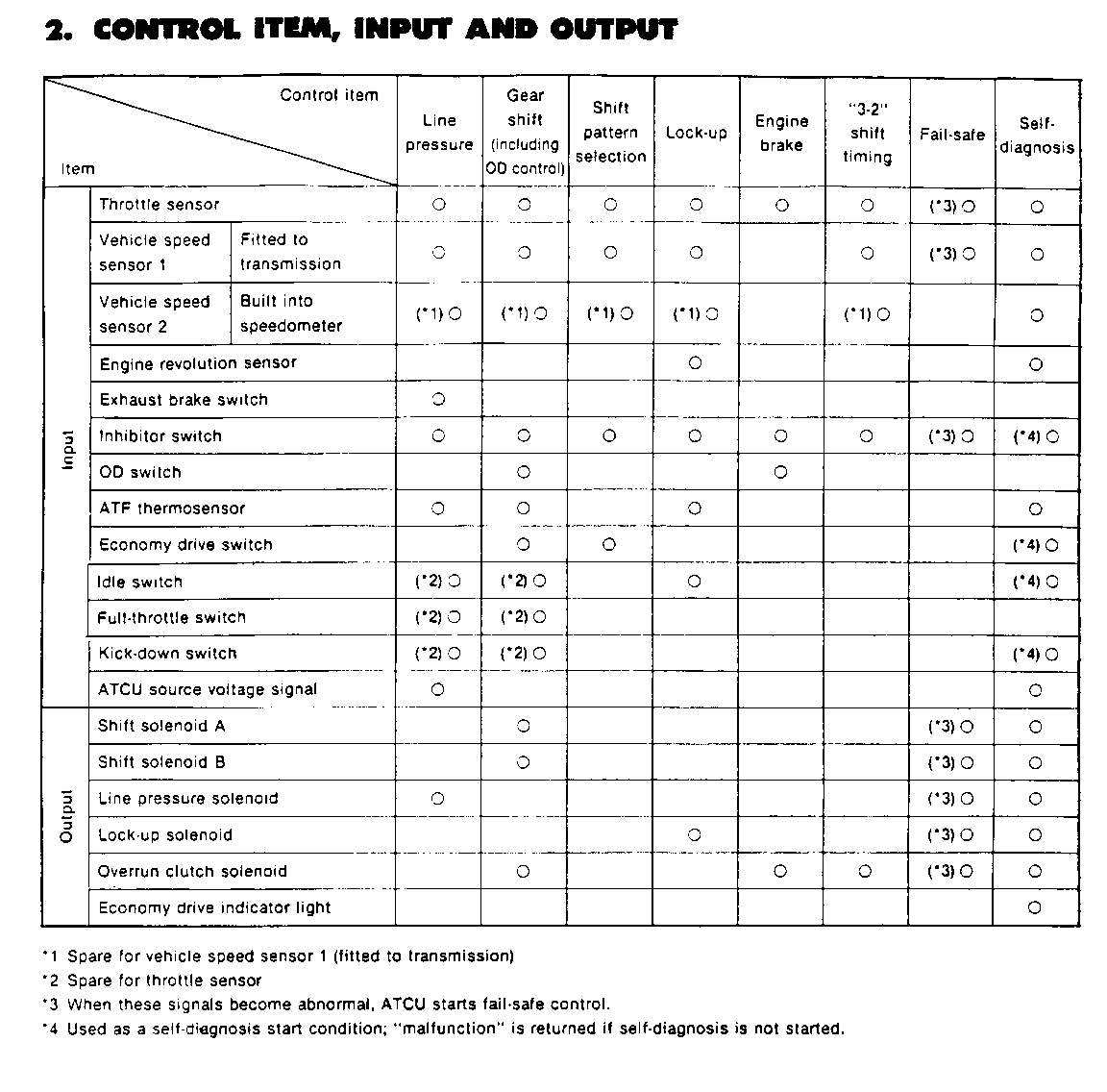
When the exhaust brake is in use, the line pressure regulating level is increased to ensure necessary clutch capacity.
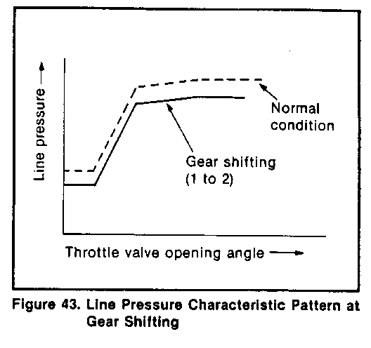
Line pressure control at the time of gear shifting (Figure 43)
In order to ease the gear shifting shock, the line pressure parameters at the time of clutch switching (shift solenoid switching) are set at appropriate levels according to the engine torque.
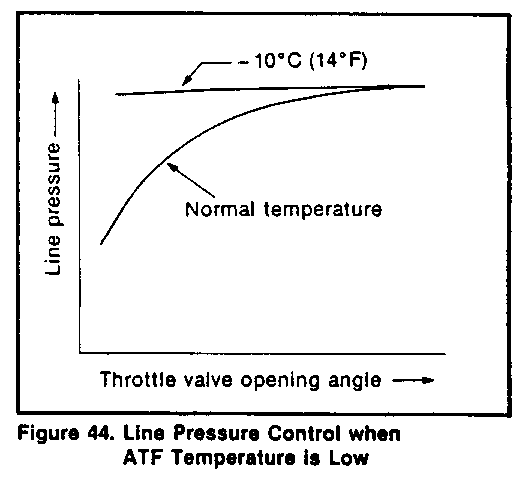
Line pressure control when the ATF temperature is low (Figure 44)
o When the ATF temperature is lower than a preset level ( - 100C or 140F), the line pressure is set at the maximum level regardless of the throttle position in order to ensure quicker operation of the clutch, brake and other friction units.
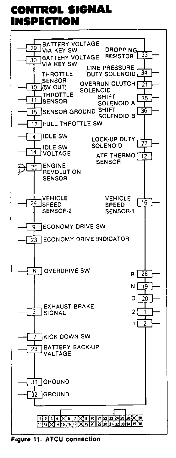
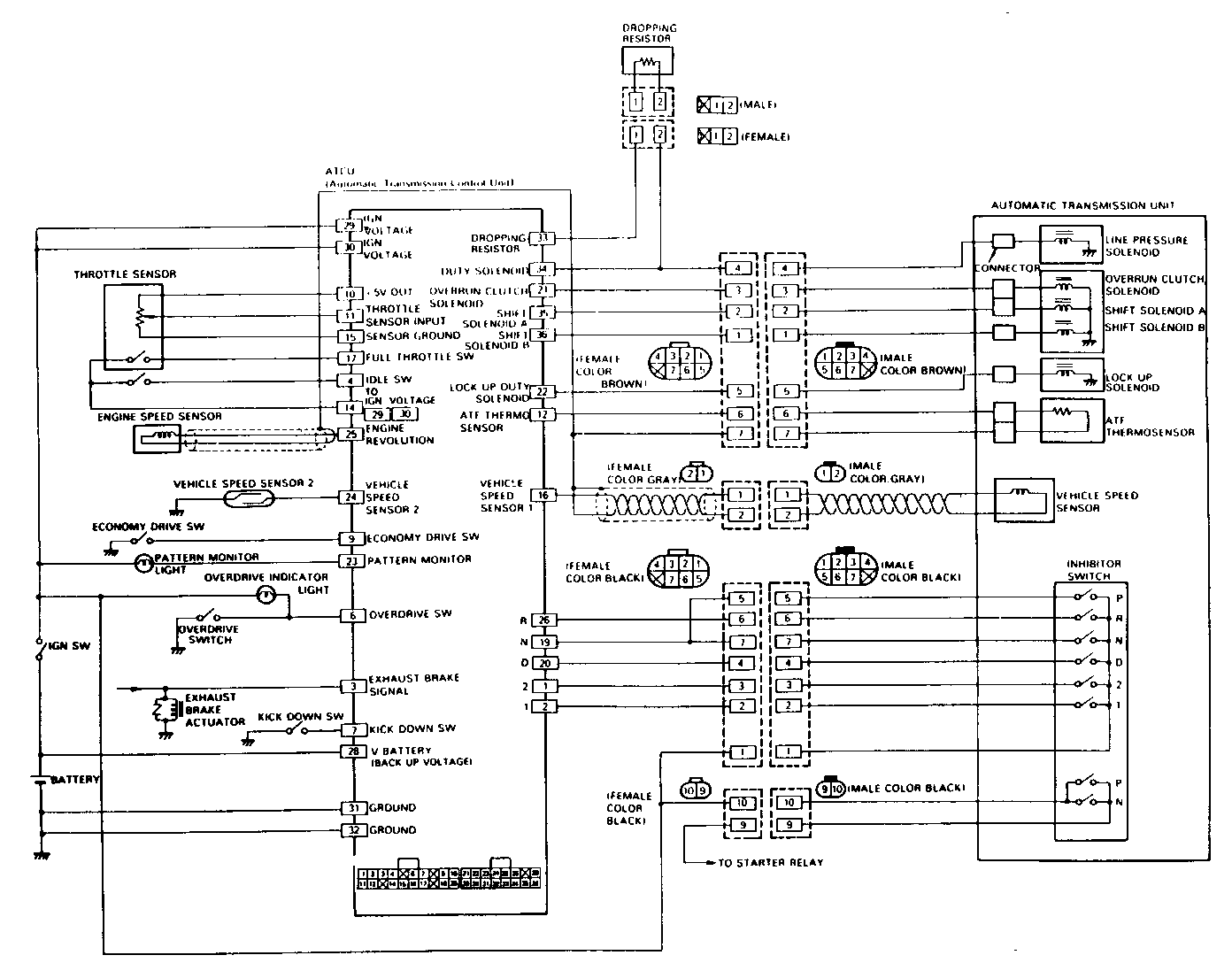
CONTROL SIGNAL INSPECTION
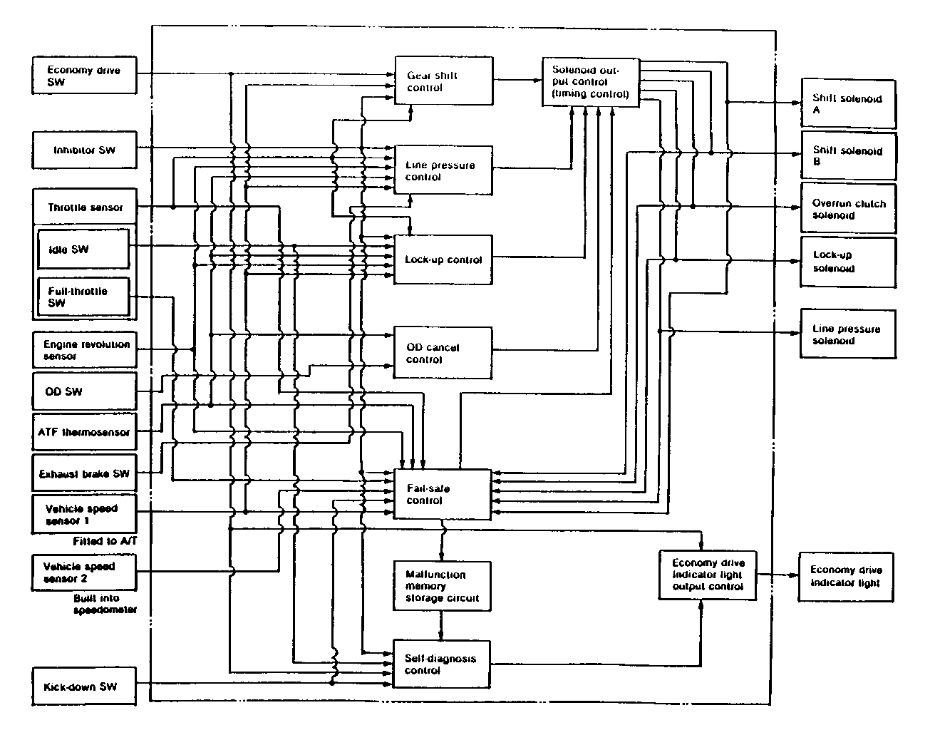
Control signal inspection is done to check for transmission and ATCU problems which cannot be detected by self diagnosis. Additionally, it serves as a back-up check for self diagnosis.
Measure the voltage drop and make a continuity test for each of the sensors, solenoids, and switches.
If the voltage is within the specified range and continuity exists, that particular area of the ATCU and automatic transmission assembly is normal.
If voltage deviation or lack of continuity is discovered, disconnect the applicable parts and check each of them individually.
This will allow you to determine the trouble location (ATCU, automatic transmission unit, or another area of the vehicle).
INSPECTION TOOL
Use a circuit tester to measure voltage and circuit continuity.
Refer to the following table for the specified voltage ranges.
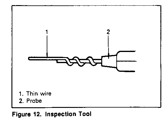
ATCU terminals are extremely small.
Wrap a piece of thin wire (1) around the probe of tester (2) (figure 12).
This will make measurement easier.
LINE PRESSURE TEST
The line pressure test checks oil pump and control valve pressure regulator valve function. It will also detect oil leakage.
Line Pressure Test Procedure
1. Check the level of the engine coolant, the engine oil, and the automatic transmission fluid.
Replenish if required.
2. Set the parking brake.
3. Place chocks at the front and rear of each tire.
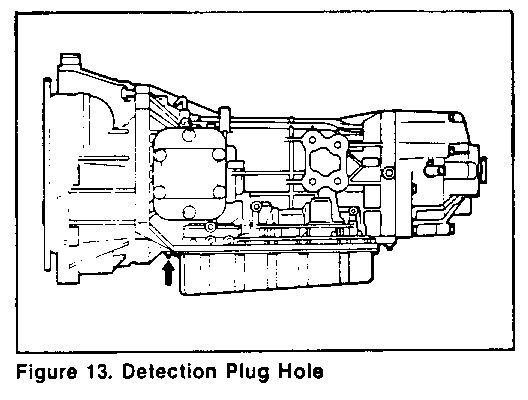
4. Remove the pressure detection plug at the bottom of the converter housing (figure 13).
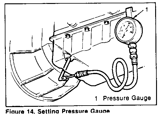
5. Set a pressure gauge (1) to the pressure detection plug hole (figure 14).
6. Start the engine and allow it to idle until the engine coolant temperature reaches 70-80 C (158-176 F).
7. Hold the brake pedal down as far as it will go.
8. Place the selector in the "D" range.
9. Note the pressure gauge reading with the engine idling.
10. Gradually push the accelerator pedal to the floor. The throttle valve will fully open.
Note the pressure gauge reading with the accelerator pedal fully depressed.
MEASURE:
Line Pressure kPa (psi) Engine Speed ---------------------------------- Range Idling Wide Open Throttle ------- ----------- ------------------ D2 & 1 294.2-470.7 882.6-961.1 (42.7-68.3) (128.0-139.4) R 470.7-706.1 1392.5-1471.0 (68.3-102.4) (201.9-213.3)
11. Release the accelerator pedal.
12. Place the selector in the "N" range.
13. Run the engine at 1,200 rpm for one minute.
This will cool the transmission fluid.
14. Repeat Steps 7-13 for the "2", " 1 ", and "R" ranges.
15. Install a new pressure detection plug to the converter housing.
16. Tighten the pressure detection plug.
TIGHTEN:
o Detection Plug: 7.3 N-m (5.4 lb.ft)
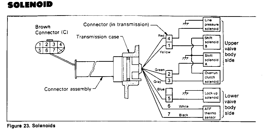
INSPECTION: (Figure 23)
Use a circuit tester to measure the resistance between the following connector terminals and ground.
MEASURE:
Solenoid Terminal Resistance No. --------------------- ------ ------------- Shift solenoid B 1 20 - 30 Shift solenoid A 2 20 - 30 Overrun clutch solenoid 3 20 - 30 Line pressure solenoid 4 2.5-5.0 Lockup solenoid 5 10 - 16
If either of the measured values are not in the specified range, the solenoid must be replaced.
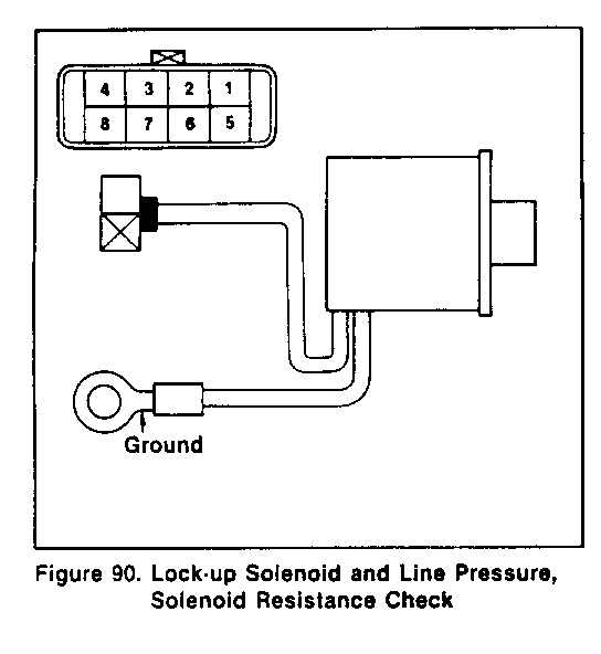
INSPECT THE SOLENOID: (Figure 90 and 91) ----------------------------------------- 1. Check resistance across the lock-up solenoid and line pressure solenoid terminals using a circuit tester (figure 90).
Standard values
Item/ Resistance Solenoid name Terminals --------------- -------------- ------------- Line pressure No. 4 - Ground 2.5 - 5 solenoid Lock-up No. 5 - Ground 10 - 16 solenoid
2. Inspect 0-rings for damage and filters for clogging.
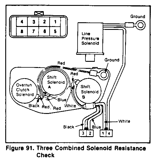
3. Check resistance across the three combined solenoid (overrun clutch solenoid, shift solenoid A, B) terminals using a circuit tester (figure 91).
Standard values
Item/ Terminals Resistance Solenoid Name ---------------- -------------- ----------- Shift solenoid A No. 2 - Ground 20 - 30 Shift Solenoid B No. 1 - Ground 20 - 30 Overrun clutch No. 3 - Ground 20 - 30 Solenoid
4. Inspect 0-rings for damage and filters for clogging.
INSPECT THE ATF THERMOSENSOR (Figure 92)
1. Put the ATF thermosensor into the ATF and check resistance across terminals, as you change the oil temperature.
Standard values
Temperature (C / F) Resistance ------------------ -------------- 20 / 68 2,500 approx. 80 / 176 300 approx.
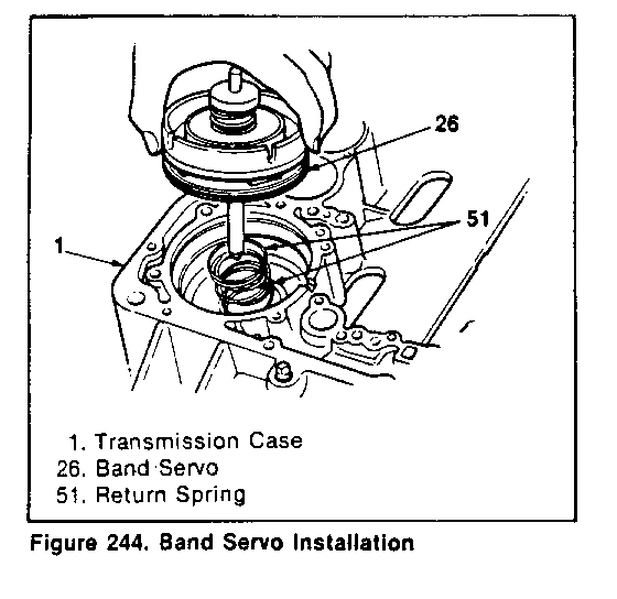
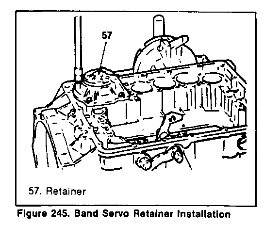
INSTALLATION OF THE BAND SERVO (Figure 244 and 245)
1. Put two return springs into the case (figure 244).
2. Apply ATF to the outer surface of the piston and inside the case, and push the piston by hand into the case.
3. Install the new gasket.
4. Install the retainer and fasten it with bolts (figure 245).
TIGHTEN - Retainer bolts 8 Nm (6 ft.lb.)
IMPORTANT: Install the retainer in the right direction. See figure 245.
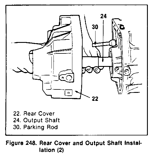
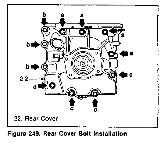
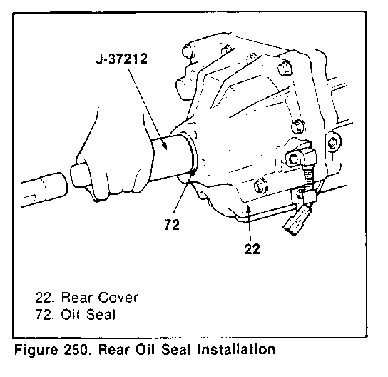
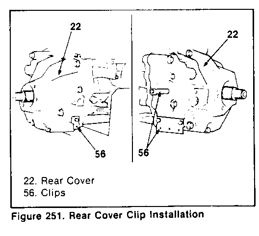
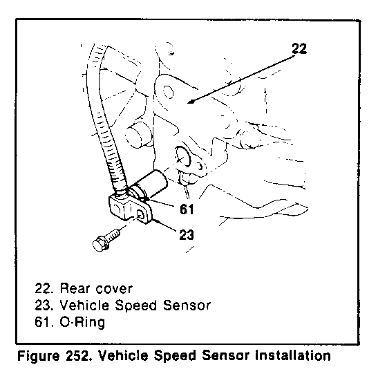
INSTALLATION OF THE REAR COVER (Figure 248, 249, 250, 251 and 252)
1. Install the new gasket.
2. Install the ear cover to the case (figure 248).
IMPORTANT: Be sure to insert the parking rod into the parking pawl.
3. Attach the rear cover with the proper new bolts, paying attention to the lengths (figure 249).
LENGTH AND QUANTITY OF THE BOLTS
Chart Length of shank mark (mm/in) Quantity ----- ---------------- --------- a 50/1.97 4 b 85/3.35 3 c 115/4.53 3 d 115/4.53 (with hole) 1
Tighten - Rear cover bolts 65 N-m (48 ft-lb)
4. Apply Vaseline to the outer surface of the new oil seal and inner circle of the rear cover.
5. Install oil seal to the rear cover using a installer (figure 250). Rear Oil Seal Installer: J-37212
6. Attach three clips (figure 251).
TIGHTEN - Clip bolts 6 N-m (4.5 ft-lb)
7. Apply Vaseline to the new 0-ring then attach to the vehicle speed sensor (figure 252).
8. Attach the vehicle speed sensor to the rear cover and fasten it with the bolts.
TIGHTEN - Vehicle speed sensor 6 N-m (4.5 ft-lb)
INSTALLATION OF THE FORWARD CLUTCH ASSEMBLY (Figure 253 and 254)
1. Remove the tape which was used to prevent the forward clutch assembly from spreading from the low one-way clutch seal ring, and push the seal ring into the groove using Vaseline (figure 253).
General Motors bulletins are intended for use by professional technicians, not a "do-it-yourselfer". They are written to inform those technicians of conditions that may occur on some vehicles, or to provide information that could assist in the proper service of a vehicle. Properly trained technicians have the equipment, tools, safety instructions and know-how to do a job properly and safely. If a condition is described, do not assume that the bulletin applies to your vehicle, or that your vehicle will have that condition. See a General Motors dealer servicing your brand of General Motors vehicle for information on whether your vehicle may benefit from the information.
