SER. MAN. UPD.-SEC.6A6,6C1,6C3 HEADBOLT TORQUE/HOT PLUG CRACK

SUBJECT: HEADBOLT TORQUE/HOT PLUG CRACK SPECIFICATION FOR ALL 1992 ISUZU W4, W4-SC, AND W4-FL MODELS.
The following represents revised information for Sections 6A6, 6Cl, and 6C3 in the 1992 W4 Service Manual.
SERVICE INFORMATION
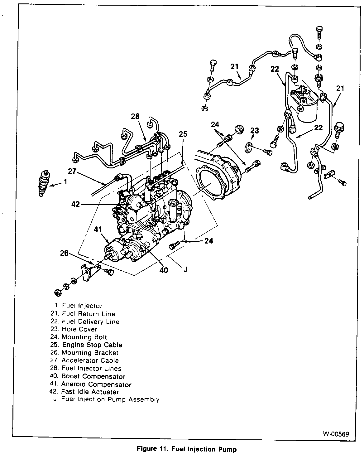
The attached pages contain revised information for the 1992 W4 Service Manual. Pay special attention to the addition of a specification for hot plug cracks on page 6A6-24 and 6A6-25. The specifications for tightening head bolts has also changed. Refer to pages 6A6-29, 6A6-30, and 6A6-66. The procedure for adjusting the hand throttle has changed to ensure proper adjustment. Refer to page 6Cl-7. Note the labeling change of the boost compensator and the aneroid compensator on page 6C3-11. Please void the existing pages and insert the new pages in your 1992 W4 service manual as follows:
Section 6A6 ISUZU ENGINE Pages: 0 6A6-24 0 6A6-25 0 6A6-29 0 6A6-30 0 6A6-66
Section 6Cl FUEL SYSTEM Page: 0 6Cl -7
Section 6C3 FUEL INJECTION SYSTEM Page: 0 6C3-11
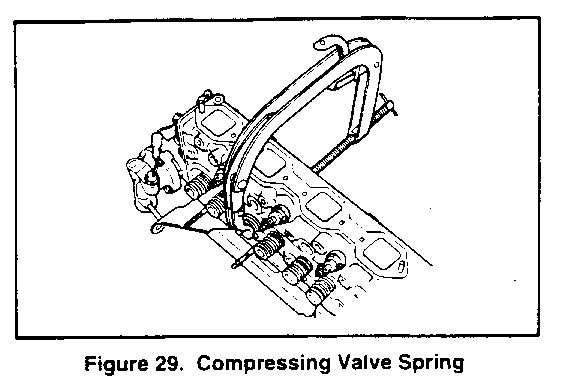
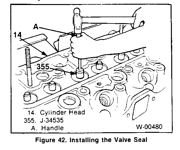
3. Thermostat housing from front of cylinder head. Refer to ON-VEHICLE SERVICE: COOLING SYSTEM COMPONENTS (SEC. 681). 4. Compress valve spring with spring compressor tool (figure 29) and remove split collars (71). 5. Valve spring (68, 69) and valve seats (70). 6. Spring seat (67). 7. Valves (65, 66). 8. Valve seal (75). Seal f its over valve guide and is retained with a spring (74).
Clean (Figure 27) - All carbon from valve ports and combustion chambers. - Valve guide bore of dirt and carbon. - Valve stems and heads. Do not use a wire wheel. - All traces of old gaskets from cylinder head (14) and block.
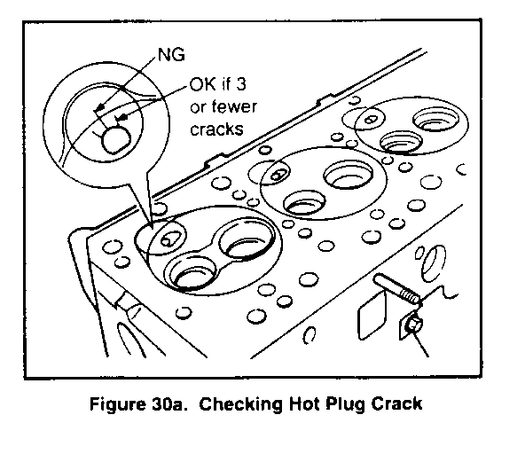
Inspect (Figure 27) - Cylinder head (14) for cracks, damaged threaded parts, etc. - Cylinder head (14) gasket surface for damage. - Valves (65 and 66) for warping, pitting, etc. - Valve seats (72 and 73) for burning and pitting. - Hot plug (76) for cracks. Replace with new parts if four or more cracks exist or if a crack extends out- side of the cylinder bore (figure 30a).
Measure (Figures 27 and 30-37)
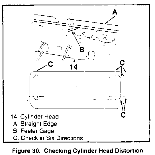
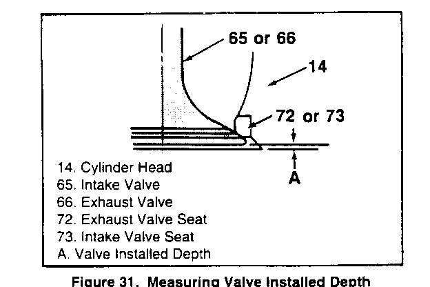
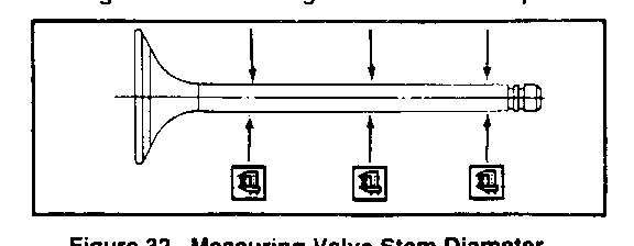
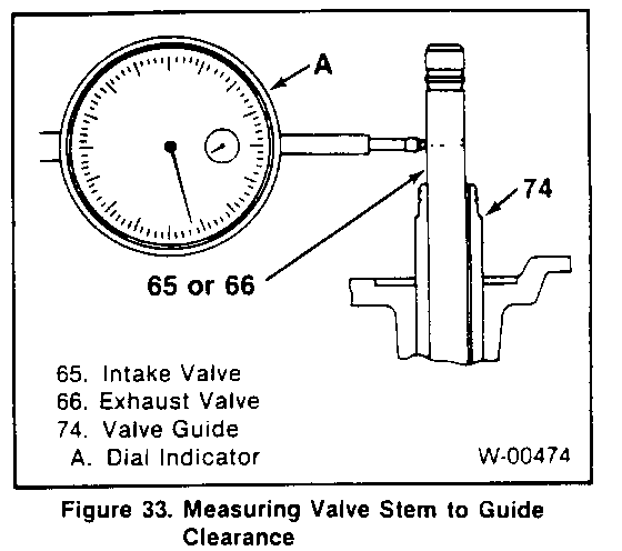
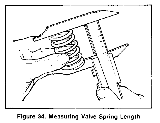
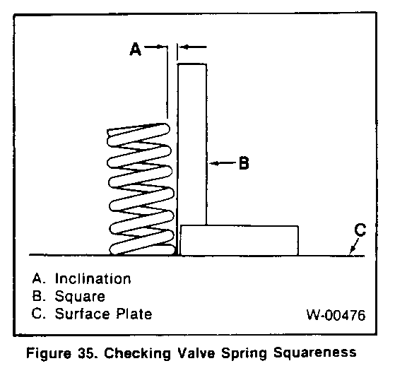
- Cylinder head gasket surface for distortion. Use a straight edge and feeler gage as shown in figure 30. Check in six different directions, as shown. If the cylinder head is distorted more than 0.2 mm (0.008 inch), it must be replaced or resurfaced. The minimum allowable thickness of the cylinder head (item M, figure 27) after resurfacing is 89.75 mm (3.533 inches). - Hot plugs for depression. Check the amount of depression of hot plugs on No. 1 through No. 4 cylinders using a feeler gage with a straightedge held against the hot plug face. If the hot plug is depressed more than 0.02 mm (0.0008 inch), it must be replaced. - Valve installed depth (figure 31). Production depth is 0.65 - 1.10 mm (0.026 - 0.043 inch). If more than 2.5 mm (0.100 inch), replace the valve (65 or 66) or valve seat (72 or 73) as required. - Valve stem diameter, as shown in figure 32. Check in three places, as shown. Check against "Specifications" at the end of this section. - Valve guide (74) inside diameter, using an inside micrometer. Check against "Specifications" at the end of this section. - Valve guide to valve stem clearance (figure 33). * Locate a dial indicator as shown. * Hold the valve on its seat. * Move the valve stem from side to side to obtain the clearance reading. Check against "Specifications" at the end of this section. - Valve springs (68 and 69) for length and straightness. Check against "Specifications" at the end of this section. -Check length with vernier calipers (figure 34). -Check amount of inclination from vertical with a square on a surface plate, as sown in figure 35. - Valve spring tension (figure 36). Check the spring at the specified length.
2. Valves (65 and 66) into the proper port. 3. Valve spring seats (67). 4. Valve springs (68 and 69). The close-spaced coils face toward the cylinder head. 5. Valve spring cap (70). 0 Compress the valve springs using spring compressor tool (figure 29). 6. Valve keys (71). Slowly release the compressor tool after the valve keys (71) are in place. 7. Thermostat housing and gasket. Refer to ON. VEHICLE SERVICE: COOLING SYSTEM COMPONENTS (SEC. 6B1) 8. Intake manifold and gasket. Refer to "Intake Manifold Replacement" earlier in this section.
Install or Connect (Figures 27 and 43-45)
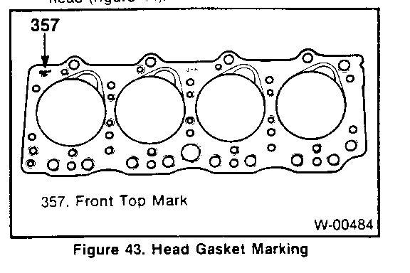
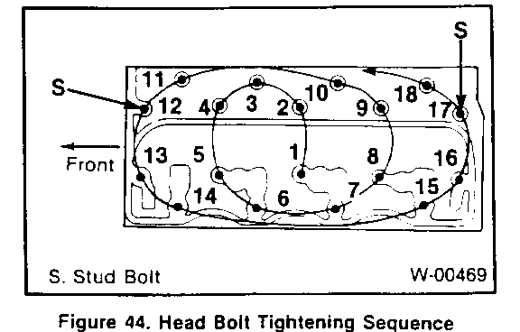
1. Head gasket (63) to the block. The "FRONT-TOP" mark on the gasket must be right side up, at the front of the block (figure 43). 2. Cylinder head (14). 0 If hot plug fell off, apply grease to tile hot plug, and install it to the cylinder head. 0 Apply grease containing molybdenum disulfide to all head bolts (64). 3. Head bolts (64). The stud bolts are used on the right side (injection pump side) of the cylinder head (figure 44).
Tighten (Figures 27, 44, and 45)
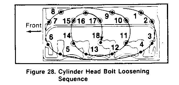
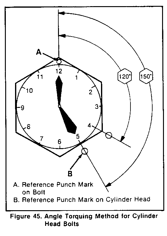
Head bolts (64) in three stages, as outlined below: 0 Stage 1: Tighten all head bolts to 68 N-m (50 ft. lbs.) using the tightening sequence shown in figure 44. 0 Stage 2: Tighten all headbolts to 88N-m (65 ft. lbs.) using the tightening sequence shown in figure 44. 0 Stage 3: Refer to figure 45. Make punch mark on the bolt heads, as shown. Then, make a second punch mark on the head, 120-150 degrees clockwise from the first mark, as shown. Then, tighten all head bolts 1 20-150 degrees, using the tightening sequence shown in figure 44.
4. Valve train components as outlined in "Valve Train Component Replacement" previously in this section.
Adjust Refer to VALVE ADJUSTMENT (SEC.6A) in this manual.
5. Cylinder head cover (36) as outlined in "Cylinder Head Cover Replacement" previously in this section. 6. Exhaust manifold (16) as outlined in "Exhaust Manifold Replacement" previously in this section. 7. Turbocharger (22) as outlined in "Turbocharger Replacement" previously in this section. 8. Injectors and injector lines. Refer to DIESEL FUEL INJECTION (SEC. 6C3) in this manual. 9. Glow plugs (56) as outlined in "Glow Plug Replacement" previously in this section. 10. Fuel filter and lines as outlined in FUEL SYSTEM (SEC. 6Cl). Engine stop cable. Refer to FUEL INJECTION PUMP REPLACEMENT (SEC. 6B3). 12. Water pump bypass hose. Refer to ON-VEHICLE SERVICE: COOLING SYSTEM COMPONENTS (SEC. 6Bl). 13. Heater hose. Refer to COOLING SYSTEM (SEC. 6B1). 14. Crankcase breather as outlined in "Crankcase Breather Replacement" previously in this section. 15. Upper radiator hose. Refer to COOLING SYSTEM (SEC. 6B1). - Fill the radiator with the proper quantity and grade of coolant. Refer to MAINTENANCE AND LUBRICATION (SEC. OB) in this manual. 16. Battery cables. 0 Bleed the fuel system. Refer to DIESEL FUEL INJECTION (SEC. 6C3) in this manual.
PISTON CONNECTING ROD AND LINER
Refer to "Statement on cleanliness and Care" Previously mentioned in this section.
Remove or Disconnect (Figures 46 and 47)
1. Battery cables. 2. Cylinder head (14) as outlined in "Cylinder Head" previously in this section. 3. Oil pan (134) as outlined in "Oil Pan Replacement" later in this section. 4. Bolts (83). 5. Connecting rod cap (82). 6. Piston (80) and connecting rod (81) as an assembly. If the piston is to be reused, mark the cylinder number on it so it can be returned to the proper cylinder as assembly. Be sure to keep the connecting rod cap (82), connecting rod (81) and connecting rod bearing inserts (86 and 87) together as a matched set. Numbers are stamped on the connecting rod and cap to help keep the parts together (figure 47).
Disassemble (Figures 46, 48 and 59) Rings (76, 77, and 78), using a ring expander (figure 48). 2. Snap rings (79). 3. Piston pin (84). Heat the piston (80), if required, to aid in piston pin removal. Do not drive the piston pin out.
Clean (Figure 46) - Piston (80) and rings (76, 77, and 78) in solvent. Do not wire brush the piston. - Liner (89) bore with a solvent soaked cloth (figure 59). - Piston (80) ring grooves with a ring groove cleaning tool.
SPECIFICATIONS GENERAL SPECIFICATIONS
MODEL 4BD2-TC TYPE In-line 4, 4-stroke INDUCTION Intercooled Turbocharger COMBUSTION CHAMBER-TYPE In-Direct Injection BORE 102 mm (4.02-) STROKE 118 mm (4.65") DISPLACEMENT 3.85 L (235.2 cu in.) COMPRESSION RATIO 21:1 FIRING ORDER 1-3-4.2 VALVE CLEARANCE, COLD 0.4 mm (0.016') IDLE SPEED (CURB IDLE SPEED) M/T 650 rpm A/T 650 rpm (in "D" Position) OIL CAPACITY Drain and Refill 11. 2 L (2.96 gal.) With Full-Flow Filter Bypass Filter Capacity
OIL PRESSURE (MINIMUM AT IDLE) 96 kPa (14 psi)
COMPRESSION PRESSURE @200 RPM Production 3043 kPa (441 psi) Service Limit 2160 kPa (313 psi) or equivalent
TORQUE SPECIFICATIONS SPECIAL TORQUES*
First Second Third Fastener Stage Stage Stage
Cylinder Head Bolts 68 N-m 88 N-m 120-150 (50 ft. lbs.) (65 ft. lbs.) degrees
Connecting Rod Bolts 39 N-m 60-90 (29 ft. lbs.) degrees
Flywheel Bolts 39N.m 60-90 (29 ft. lbs.) degrees
* See Text For Tightening Procedure. Refer to figure 45, 70, 100a.
HAND THROTTLE ADJUSTMENT
Before adjusting the hand throttle cable be sure the accelerator linkage and engine idle speed are adjusted correctly.
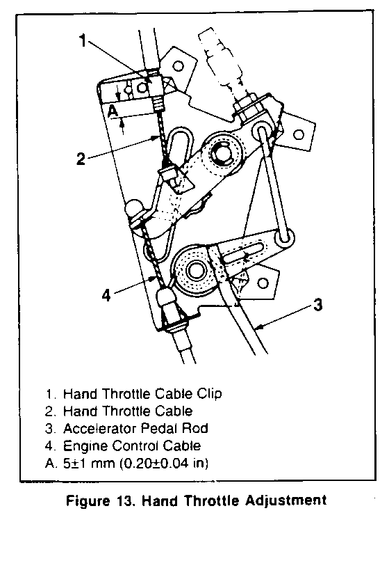
Adjust (Figure 13)
1. Position the hand throttle control knob in the "off" position.
2. Loosen the clip (1) and adjust the cable (2) so that there is 5+/-l mm (0.20+/-O.04 in) clearance (A) between the clip and the outer cable end.
3. Tighten the clip (1) to hold the cable in position.
4. From the position above, confirm that the accelerator pedal begins to move when tile hand throttle control knob is turned 2.5 times.
General Motors bulletins are intended for use by professional technicians, not a "do-it-yourselfer". They are written to inform those technicians of conditions that may occur on some vehicles, or to provide information that could assist in the proper service of a vehicle. Properly trained technicians have the equipment, tools, safety instructions and know-how to do a job properly and safely. If a condition is described, do not assume that the bulletin applies to your vehicle, or that your vehicle will have that condition. See a General Motors dealer servicing your brand of General Motors vehicle for information on whether your vehicle may benefit from the information.
