CAMPAIGN:TICS FUEL INJ. PUMP EROSION IN FUEL PUMP HOUSING

SUBJECT: TICS FUEL INJECTION PUMP EROSION IN THE FUEL PUMP HOUSING
MODELS: 1992-1994 GMC FORWARD AND CHEVROLET TILTMASTER W5-W7 SERIES WITH THE 6BG1-TC ENGINE AND ELECTRONIC TIMING AND INJECTION RATE CONTROL SYSTEM (TICS).
General Motors has determined that CERTAIN 1992, 1993 and 1994 W5-W7 Series may, experience erosion in the fuel injection pump housing. Analysis has shown erosion to be the result of cavitation in the fuel injection pump housing. Erosion could eventually allow diesel fuel to leak into the engine crankcase causing oil dilution.
Vehicles affected by erosion may experience:
* Increased crankcase oil levels
* Decrease in fuel economy
* Poor acceleration
To correct this condition. the fuel injection pump and fuel return pipe will need to be replaced. In addition, if the vehicle did not have a fuel pipe modification completed from Product Campaign Bulletin 93-C-02, dated November 1992, the modification will also need to be completed at this time and is included in the labor time allowance of this bulletin. Dealers are also required to complete an oil and oil filter (vehicle is equipped with two oil filters) change free of charge to the customer. This oil and filter change is only valid at time of fuel injection pump replacement under this product campaign and is also included in the labor time allowance of this bulletin. THERE ARE TWO (2) OIL, FILTERS AND THE PART NUMBERS ARE: 94037791 AND 94054123.
VEHICLES INVOLVED
Involved are CERTAIN 1992-1994 W5-W7 series built within the following VIN breakpoints:
YEAR MODEL FROM THROUGH ---- ----- ---- ------- 1992 W5 N3000003 N3002274 W6 N3100007 N3100845 W7 N3200004 N3202284 W7HV N3300003 N3300576 W7T N3400002 N3400008
1993 W5 P3000001 P3002275 W6 P3100001 P3101154 W7 P3200002 P3202219 W7HV P3300001 P3300350
1994 W5 R3000011 R3001399 W6 R3100001 R3100583 W7 R3200001 R3200844 W7HV R3300002 R3300126
The specific vehicles involved in this campaign have been identified by Vehicle Identification Number Computer Listings. These listings are furnished to all involved dealers with the campaign bulletin. Dealers should confirm vehicle eligibility through VISS (Vehicle Information Service System) or SERVICENET prior to beginning campaign repairs.
DEALER CAMPAIGN RESPONSIBILITY
Unsold vehicles in dealers' possession that are subject to this campaign and appear on your VIN listing MUST be held and inspected/repaired Per the service procedure of this campaign bulletin BEFORE owners take possession of these vehicles. When repaired, all unsold vehicles in dealers' possession must include the following notice to the new truck purchaser:
NOTICE TO NEW TRUCK PURCHASER
This new vehicle has been up-graded with a new or re-manufactured fuel injection pump. As repaired, this vehicle meets General Motors' quality standards and is warranted by the new vehicle limited warranties.
These stickers will be provided to dealers and should be affixed to the inside driver's door glass with the wording facing out on the involved unsold new vehicles after the repair is completed.
Dealers are to service all vehicles subject to this campaign at no charge to owners, regardless of mileage, age of vehicle, or ownership, from this time forward. However, due to limited fuel injection pump availability, vehicle owners will be notified by staggered mailing dates every 3 months, starting with the oldest vehicles (1992) first.
Dealers are also required to complete an oil and filter change free of charge to the customer. This oil and filter change is only valid at time of fuel injection pump replacement service campaign.
Owners of vehicles recently sold from your vehicle inventory are to be contacted by the dealer and arrangements made to make the required correction according to instructions contained in this bulletin.
In summary, whenever a vehicle subject to this campaign enters your vehicle inventory, or is in your dealership for service in the future, please take the steps necessary to be sure the campaign correction has been made before selling or releasing the vehicle.
If the name and address of the owner of an involved vehicle was unavailable to GMC Truck Division at the time of campaign initiation, the dealer must determine the owner's name and address from the dealership sales records. Please provide this information directly on the second copy of the listing next to the applicable VIN so that our records may be updated and the appropriate notification mailed to the owner. This second copy should then be submitted to the address listed below in the previously supplied yellow campaign envelopes.
GMC Truck Division General Motors Corporation 101 Union Street Plymouth, Michigan 48170
OWNER NOTIFICATION
Owners will be notified of this campaign on their vehicles by GMC Truck Division (see copy of owner letter included with this bulletin), according to staggered mailing dates due to parts availability. A listing of owner names and addresses has been furnished to the involved dealers to enable dealers to follow up with owners involved in this campaign. This listing may contain owner names and addresses obtained from State Motor Vehicle Registration records. The use of such motor vehicle registration data for any other purpose is a violation of law in several states. Accordingly, you are urged to limit the use of this listing to this campaign.
SERVICE PROCEDURE
FUEL INJECTION PUMP REMOVAL
1. Park vehicle, position selector lever in neutral, turn key to off position, exit, tilt cab, position safety pin and block the front wheels.
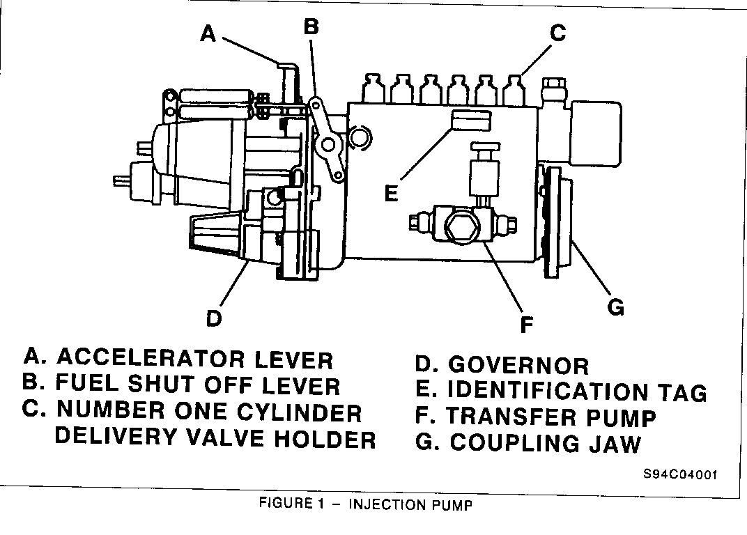
2. Make sure fuel shut off lever (Figure 1, Item B) is in the stop position (forward position), pointing toward front of vehicle.
3. Disconnect negative battery cable.
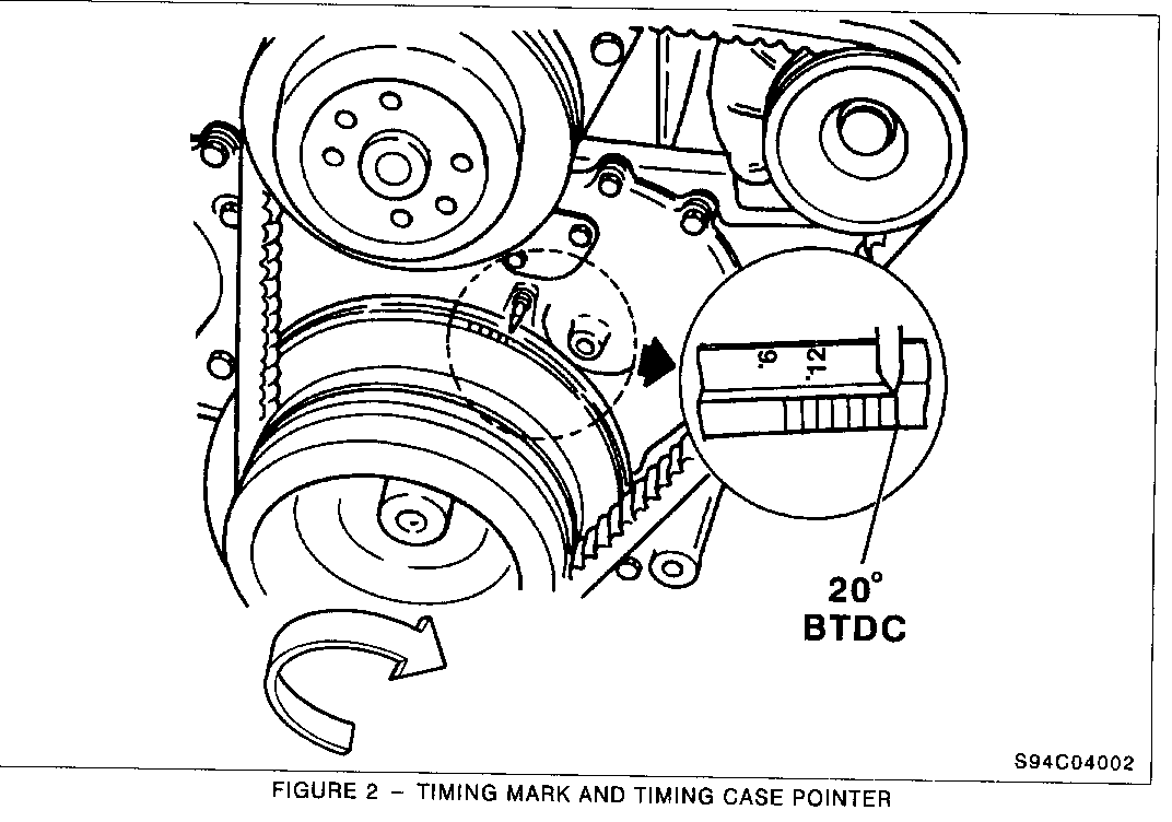
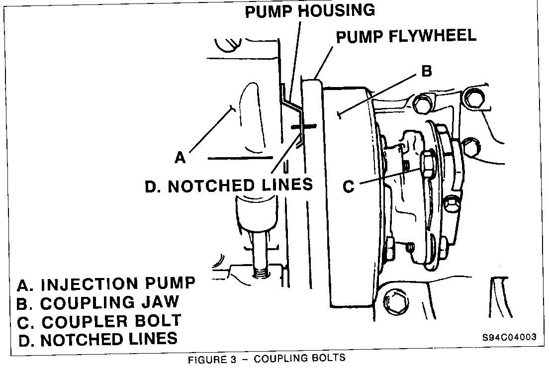
4. Rotate crankshaft clockwise until the timing indicator on engine case lines up with the 201 BTDC mark on the balancer (Figure 2). The mark on the pump flywheel and indicator on housing should line up at this point (Figure 3, Item D).
IMPORTANT: The engine pulley and the timing marks must be aligned at the same time. This insures the injection pump will be in time when the new pump is installed. (Figure 3).
5. Disconnect inject on pump wire harness at injection box.
6. Remove air inlet pipe to air cleaner assembly.
7. Remove power steering unit reservoir at frame rail and secure unit.
8. Remove passenger side mud flap. (W5 driver side and passenger side must be removed as well as the cab cross member support).
9. Remove or loosen 12 mm bolt holding transmission cable (s) from the bracket and push cables aside out of the way. Remove two (2) 12 mm bolts holding transmission cable to manifold.
10. Remove cotter pin and washer from stop cable bracket and throttle cable bracket, remove cables, replace pins and washers to studs.
11. Remove air compressor inlet line.
12. Clamp off both fuel lines from fuel tank, underside of engine.
13. Remove twelve (12) fuel return lines at injection pump.
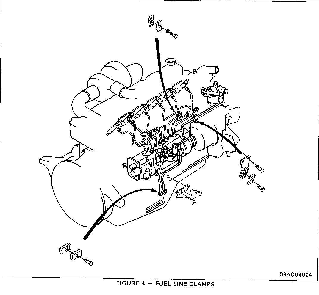
14. Remove fuel line jaw clamps from all fuel lines (Figure 4).
15. Loosen all fuel lines. Do not remove eye bolts at this time.
IMPORTANT: Use a 14 mm deep socket placed between fuel line and injection pump housing, to keep fuel line from bending. Do not remove eye bolts at this time.
16. Remove two (2) 10 mm bolts securing fuel line bracket to manifold holding fuel lines to filter. Loosely replace bolts to manifold.
17. Remove fuel lines, reinstall eye bolts to their original locations.
NOTICE: The 22 mm adapter to the engine block may turn during removal. If this happens, carefully back out the eye bolts until a 22 mm open end wrench can be secured to the engine block adapter and then remove the eye bolt.
18. Loosen injector lines at the injection pump and the fuel injectors.
19. Remove injector lines from engine.
20. Remove turbo boost line.
21. Remove oil cooler lines.
22. Loosen bolt on injection pump coupling jaw using a 19 mm open end wrench. Back out bolt far enough to free bolt from coupling to injection pump, rotate coupling 180 degrees by turning alternator pulley, loosen other bolt on coupling, again back out far enough to free bolt from coupling to injection pump, rotate coupling and engine pulley until timing marks again line up.
23. Remove four (4) bolts holding injection pump to mount and discard.
24. Remove remaining 14 mm bolts holding injection pump bracket to engine. A 14 mm socket and breaker bar may be required, using a medium size screwdriver to pry bracket off pins on side of engine.
25. Injection pump may be removed.
FUEL INJECTION PUMP REINSTALLATION
IMPORTANT: Mounting bracket must be secured to the injection pump prior to installation.
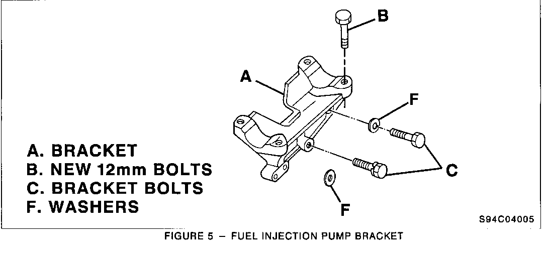
1. Install four (4) NEW 12 mm bolts to secure injection pump to mounting bracket. Torque 12 mm bolts to 20 lbs/ft or 27 Nm (Figure 5. Item B). Insure bracket is properly set on locator pins. Torque 14 mm bolts to 25 ft/lbs or 34 Nm (Figure 5. Item C).
IMPORTANT: Make sure all eye bolts are hand started with their packing gaskets properly positioned. Also torque to required specifications as outlined in this bulletin.
2. Install rear of pump first and align to coupling jaw, center injection pump on mounting bracket and move pump up and down in order to start the two 19 mm coupling bolts.
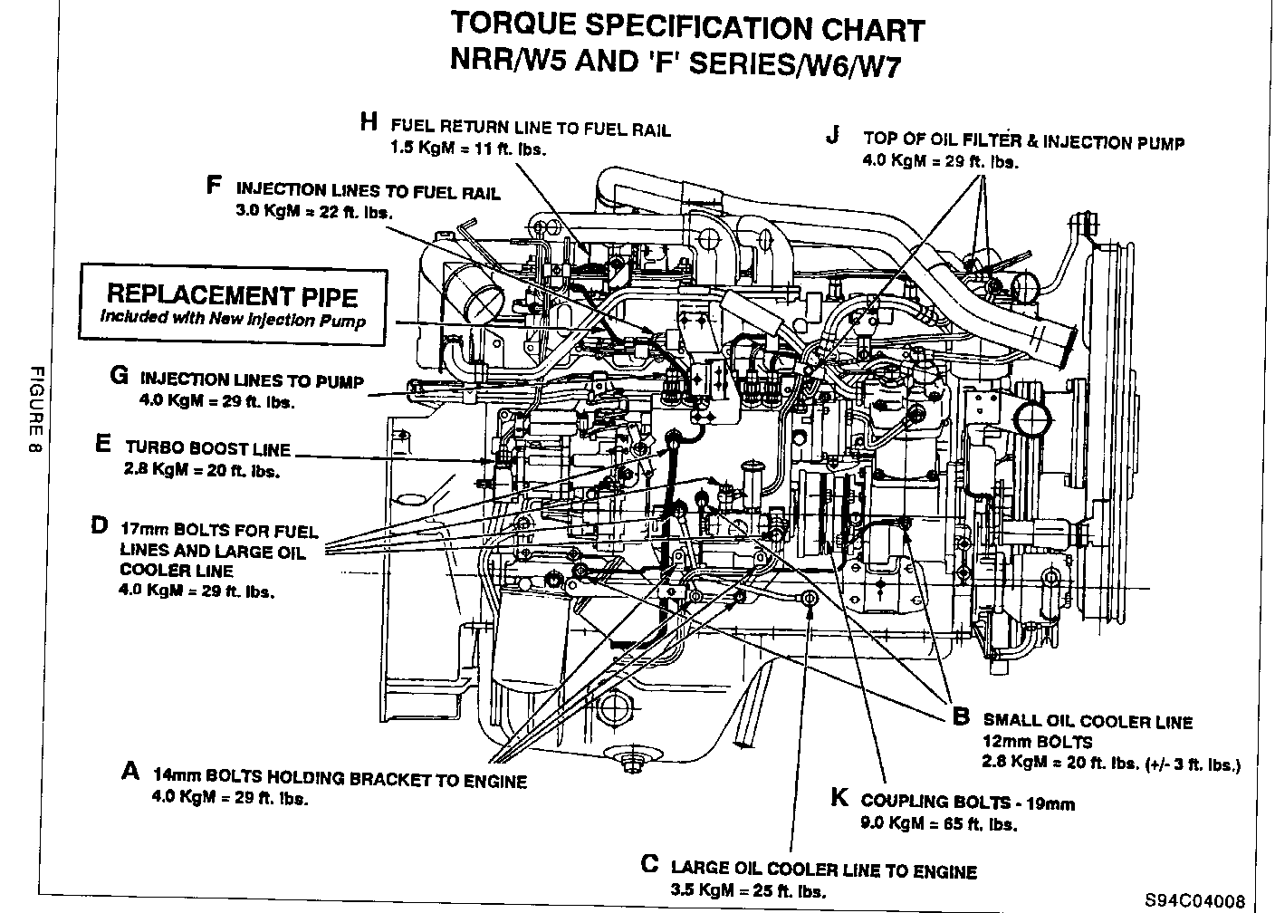
3. Torque two (2) 19 mm coupling bolts to 65 ft/lbs or 88 Nm (Figure 8. Item K).
4. Install small oil cooler line to injection pump, oil filter, and air compressor. Torque all three 12 mm bolts to 20 ft/lbs or 27 Nm. (Figure 8. Item B).
NOTICE: This oil cooler line is fragile and proper torque is important.
5. Install larger oil line to injection pump and engine. Torque oil cooler line to engine to 25 ft/lbs or 34 Nm and the oil line to injection pump to 29ft/lbs or 39 Nm. (Figure 8. Items C and D).
6. Reinstall or install fuel inlet pipe to transfer pump. Torque to 29 ft/lbs or 39 Nm (Figure 8 Item D). Refer to Product Campaign Bulletin 93-C-02 if necessary.
7. Install turbo boost line. Torque to 20 ft/lbs or 27 Nm (Figure 8. Item E).
8. Install all fuel injection lines from injection pump to fuel injectors. Torque all six (6) lines at injection pump to 22 ft/lbs or 30 Nm and all six (6) lines to injectors to 29 ft/lbs or 39 Nm. It will be necessary to use a 6" extension and 17 mm crows foot (Figure 8, Items F and G).
IMPORTANT: Part numbers listed below are ZEXEL part numbers and are included with replacement pump shipment.
9. Install the new fuel return line to the injection pump (W5 part is # 1-154-15720-0, W6-7 part is # 1-154-15719-0. Torque eye bolt at injection pump to 29 ft/lbs or 39 Nm (Figure 8. Items D and F).
10. Remove vise grip pliers from fuel tank hoses.
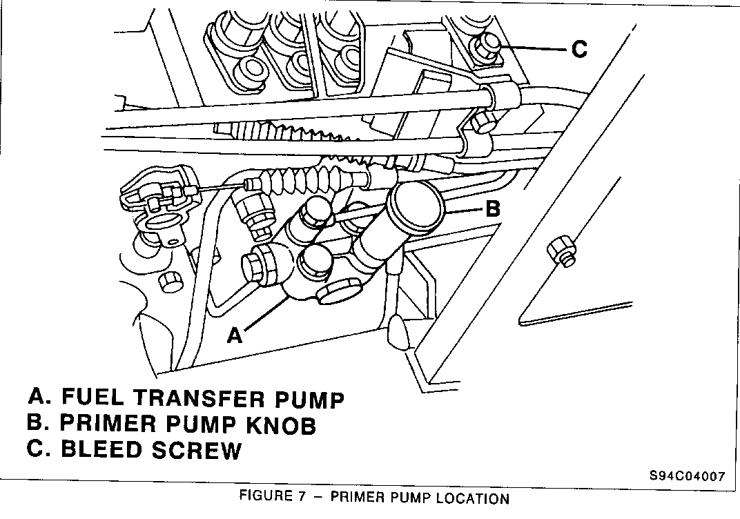
11. Loosely install fuel pipes to injection pump, transfer pump, and fuel filter. Properly position wire harness between fuel pipes. Torque the 17 mm bolts at injection pump, transfer pump and steel colored bolt at the fuel filter to 29 ft/lbs or 39 Nm (Figure 8, Item D). Leave the outlet line at the top of fuel filter loose at this time. This bolt will be torqued after bleeding procedure (Figure 7, Item C).
12. Install all jaw clamps to fuel lines (Figure 4).
13. Install pipe to air compressor and position rubber hoses and hose clamps.
14. Remove cotter pins and washers from throttle cable stud and run stop lever stud, position throttle cable over studs and reinstall washers and cotter pins.
15. Install two (2) 12 mm bolts holding cable bracket to intake manifold. DO NOT OVER TIGHTEN THESE BOLTS.
16. Install power steering reservoir to frame.
17. Remove protective inserts from new wire harness connectors and connect the gray and black connectors on wire harness.
18. Install black turbo pipe.
19. Connect negative battery cable to battery.
20. Check to insure all fuel lines are properly connected.
21. Bleed the fuel system to remove any air which has entered the system.
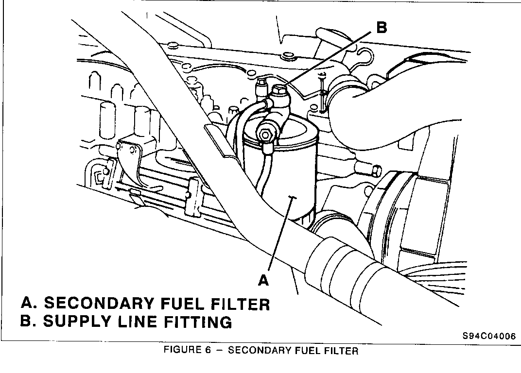
a. Unscrew the primer knob at the transfer pump and lift it up (Figure 7, Item B), also loosen bolt on top of fuel filter (Figure 6, Item B).
b. Pump the pump knob until a solid stream of fuel comes out of the fuel outlet line at top of fuel filter. Torque the fuel outlet fitting at top of fuel filter to 29 ft/lbs or 39 Nm (Figure 6. Item B).
22. Clean any spilled fuel from engine area.
23. Attempt to start engine. If the engine does not start within the first several engine cranks, stop and repeat the bleeding procedure and attempt to start engine again. Once engine starts, slowly increase engine rpm's to force fuel into engine.
IMPORTANT: Main and bypass oil filters must be changed.
24. Complete oil and filter change. Oil filter part numbers are 94037791 and 94054123.
25. Check engine for fuel leaks and correct as required.
26. Install "Campaign Identification Label" to the inside of the driver's door pillar.
PARTS INFORMATION
IMPORTANT: Please read and follow carefully.
1. Parts are to be obtained from ZEXEL through American Isuzu Motors Inc. (AIMI).
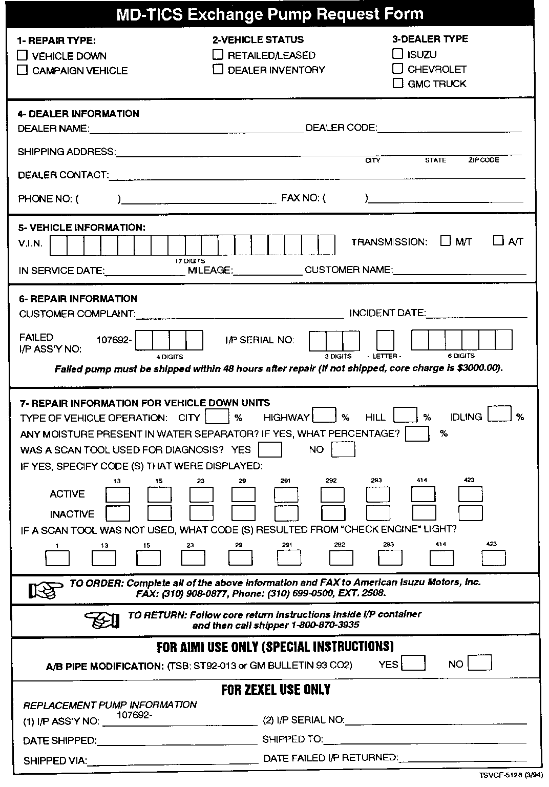
2. Dealer must fill out the "MD-TICS Exchange Pump Request Form" supplied with service bulletin 366303 dated May 1994. Fax this form to American Isuzu Motors Inc. (AIMI) National Office. A sample form is included with this bulletin.
FAX MD-TICS EXCHANGE FORM(S) TO: American Isuzu Motors Inc. FAX# (310) 908-0877
3. Allow 3 working days for delivery of New Design Fuel Injection Pump.
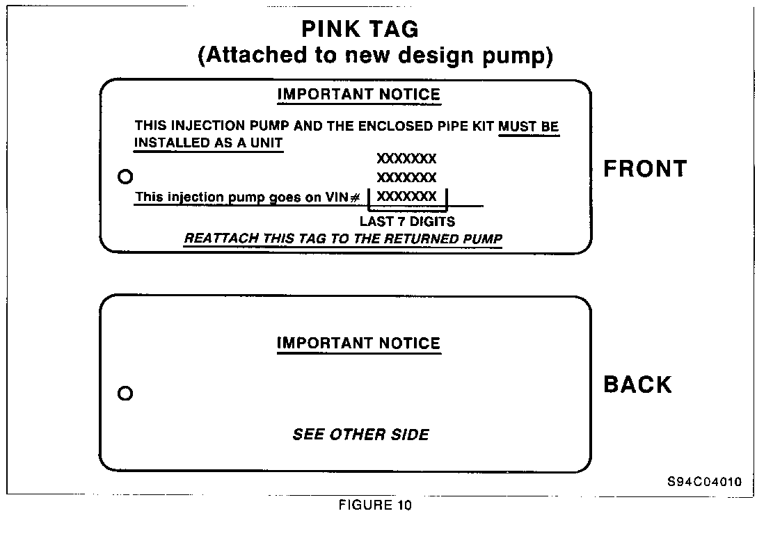
4. Upon receipt of the New Design Fuel Injection Pump, dealer will find a Pink Tag attached to the pump. The NEW DESIGN PUMP is assigned to a designated vehicle according to the Vehicle Identification Number (last 7 digits) listed on the Pink Tag (Figure 10). Included with the new design injection pump are the fuel return pipe, pipe mounting bolts and gaskets.
IMPORTANT: Do not use the New Design Fuel Injection Pump on any vehicle other than the one specified on the Pink Tag.
5. After installing new design fuel injection pump and fuel pipe, see return instructions enclosed for return labels and shipping instructions. Returned cores are essential for future pump availability. If removed pump is not returned within 48 hours of receipt of new pump, a $3,000.00 core charge will be applied.
Part Number Description Quantity ----------- ------------ -------- NPN Fuel Injection 1 94037791 Oil Filter, Main 1 94054123 Oil Filter, By Pass 1
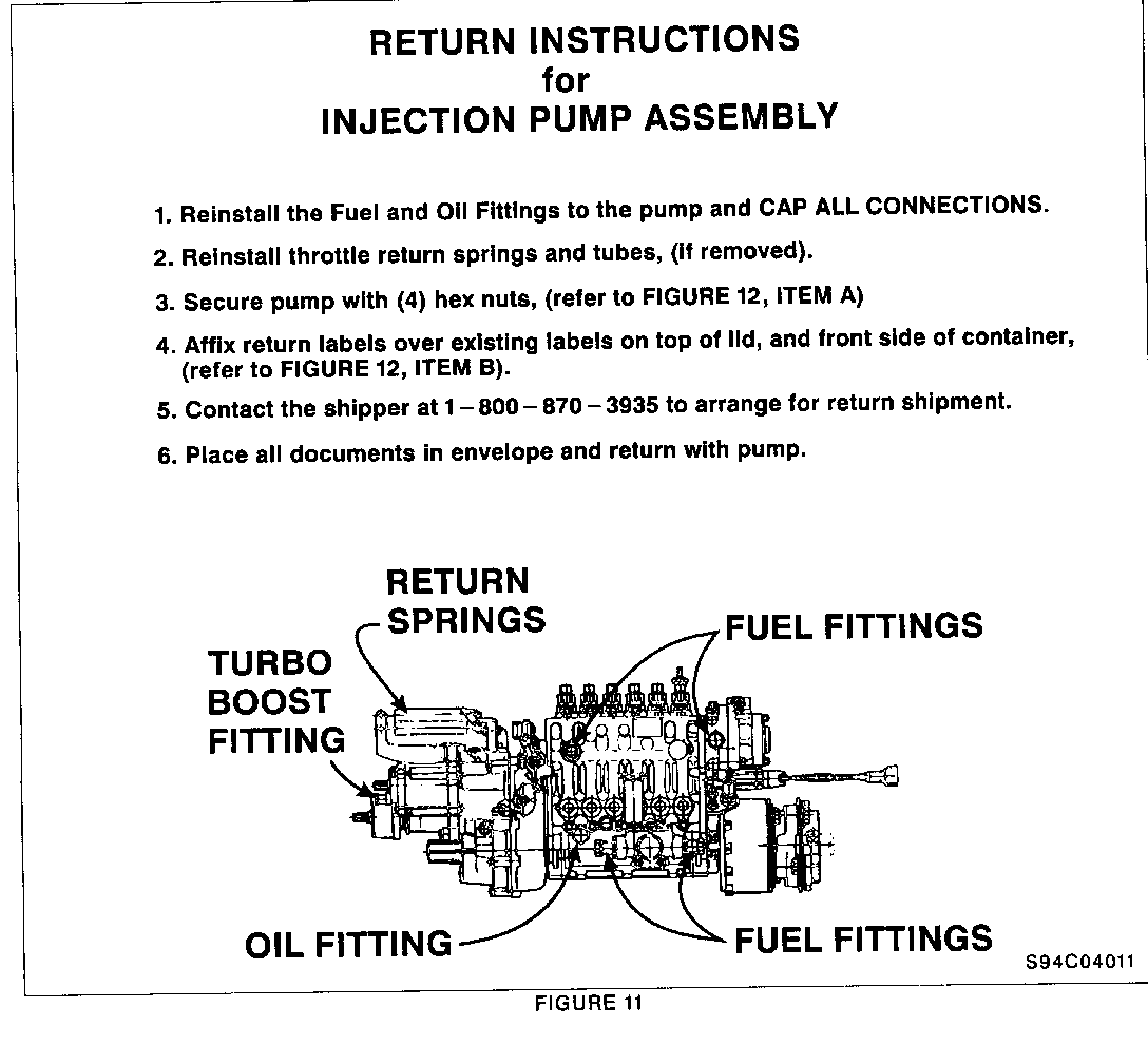
RETURN INSTRUCTIONS FOR INJECTION PUMP ASSEMBLY (See Figure 11).
1. Reinstall the fuel and oil fittings to the pump and cap all connections.
2. Reinstall throttle return springs and tubes (if removed).
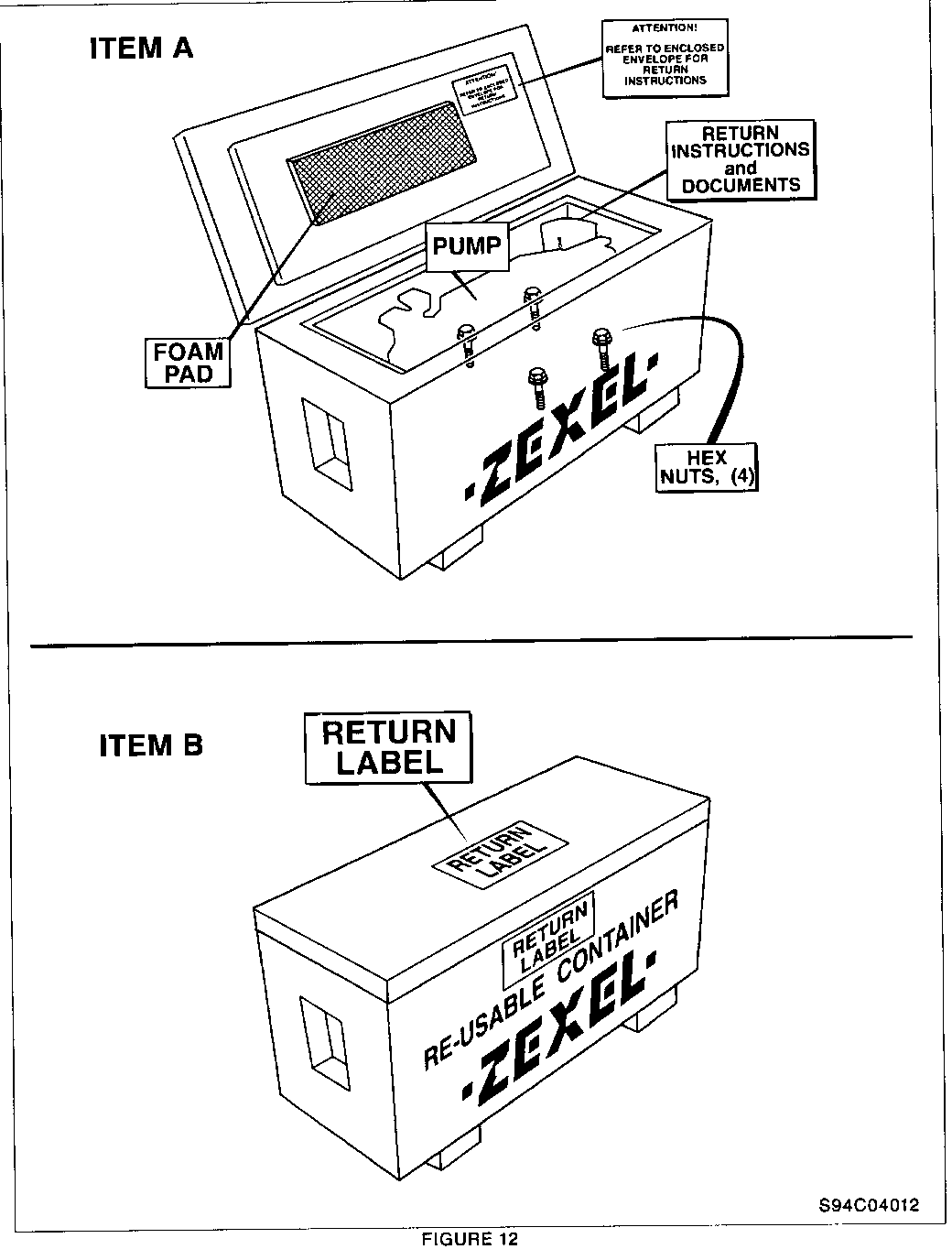
3. Secure pump with four (4) hex nuts (refer to Figure 12, Item A).
4. Affix return labels over existing labels on top of lid, and front side of container (refer to Figure 12, Item B).
5. Contact the shipper at 1-800-870-3935 to arrange for return shipment.
6. Place all documents in envelope and retum with pump.
WARRANTY INFORMATION
Dealers should submit a warranty claim on each vehicle completed under this campaign. As the fuel injection pump is supplied, no part number for the pump is to be claimed. Also, as the main and by-pass oil filters are to be claimed in Net Items with oil and parts handling allowance for the pump, no parts should be entered on the claim.
Labor Operation *Time **Parts Trouble Number Description Allowance Allowance Code ----------------------------------------------------------------------------- V8990 Remove and replace W5 fuel injection 4.6 hrs. $120.00 96 pump w/automatic transmission (includes oil and oil filter change)
V8991 Remove and replace W5 fuel injection 4.4 hrs. $120.00 96 pump w/manual transmission (includes oil and oil filter change)
V8992 Remove and replace W6-7 fuel 4.1 hrs. $120.00 96 injection pump w/automatic transmission (includes oil and oil filter change)
V8993 Remove and replace W6-7 fuel 3.9 hrs. $120.00 96 injection pump w/manual transmission (includes oil and oil filter change)
* Above labor time includes: Injection pump remove and replace, change engine oil and filters, install new fuel return line and install transfer pump fuel line (if necessary). For dealer to receive administrative time allowance associated with this campaign, add 0.1 hour to the Labor Operation Time Allowance.
** The $120.00 amount identified in the "Parts Allowance" column represents a handling allowance for the injection pump furnished in this campaign + 15.5 qts of engine oil and filters. This amount is to be placed in the Net Item Amount column and type code "M."
CAMPAIGN IDENTIFICATION LABEL
Each vehicle corrected in accordance with the instructions outlined in this Product Campaign Bulletin will require a "Campaign Identification Label." Each label provides a space to include the campaign number and five (5) digit dealer code of the dealer performing the campaign service. This information may be inserted with a typewriter or ball point pen. Each "Campaign Identification Label" is to be located on the inside of the driver's door pillar in an area which will be visible when the vehicle is brought in for periodic servicing by the owner.
Apply "Campaign Identification Label" only on a clean, dry surface.
ADMINISTRATIVE PROCEDURE
Procedures covering this campaign are outlined in Section V of your dealership's "GMC Truck Warranty Claims Processing Manual" #P9119.
Dear GM Truck Owner:
As a valued customer, your complete satisfaction with your GM Medium Duty truck is our goal. In keeping with this goal, we want to let you know that we have discovered a problem that could affect your vehicle and we want to take care of it at no charge to you.
On a number of 1992-1994 GMC Forward and Chevrolet Tiltmaster W5-W7 medium duty models equipped with the 6BG 1-TC 6 cylinder diesel engine, such as yours, may experience erosion in the fuel injection pump housing. This condition could result in eventual diesel fuel leakage into the engine crankcase. Vehicles effected by erosion may experience increased crankcase oil levels, decreased fuel economy and/or poor acceleration. To be absolutely sure that your vehicle is to specifications, we will replace the fuel injection pump that is installed on your engine and change your oil and oil filters.
Instructions for performing this service have been sent to your GM Medium Duty dealer, and parts will be available on your service appointment date. Please contact your GM Medium Duty dealer to arrange an appointment date for service as soon as possible. This procedure will take about 4.5 hours to complete. but you should ask how much additional time your dealer will need to schedule and process your vehicle.
The enclosed postage paid owner reply card identifies your vehicle. Presentation of this card to your dealer will assist in making the necessary correction to your vehicle in the shortest possible time. If you have sold or traded your vehicle, please furnish us the complete name and address of the person you sold or traded your vehicle to and return the card to us.
We are sorry to cause you this inconvenience; however, we have taken this action in the interest of your continued satisfaction with our product.
GMC TRUCK DIVISION GENERAL MOTORS CORPORATION
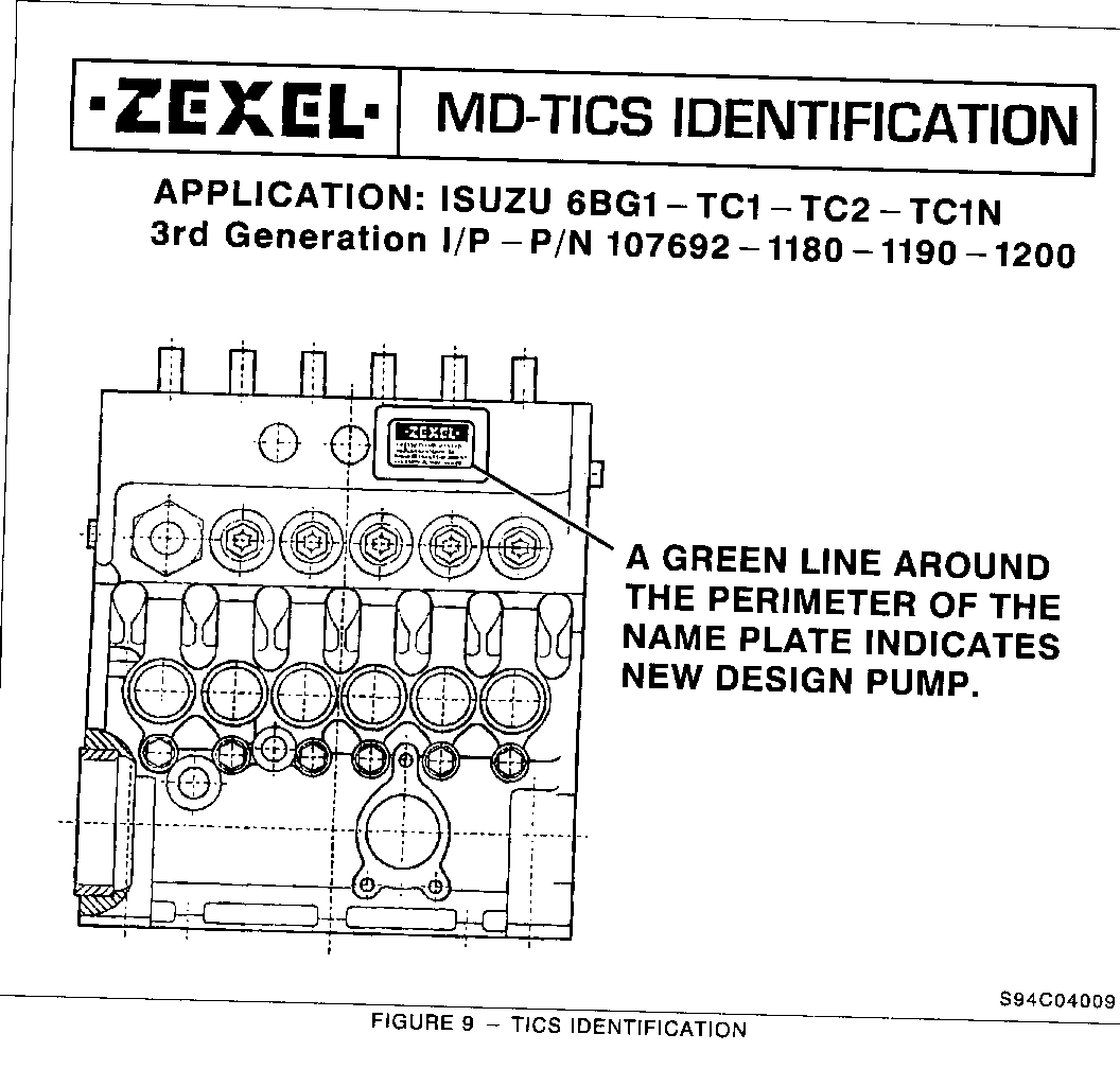
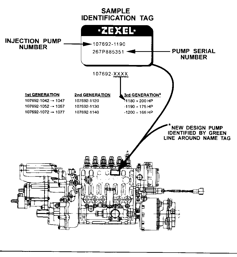
TICS FUEL INJECTION PUMP IDENTIFICATION INFORMATION
This information affects all 1992/93/94 Isuzu/GM Trucks with the 6BG1-TC engine and the electronic Timing and Injection Rate Control System (TICS).
Two Methods to identify New Design Injection Pump
1. The pump is New Design by indication of the green line painted on the side of pump label as shown below.
2. The fuel injection pump is a 166, 175, or 200 horsepower application according to the numbers 1200, 1190, and 1180.
Example:
------- Injection Pump assembly number: 107692- 1180 identifies a New Design, 200 Horse- power Fuel Injection Pump.
General Motors bulletins are intended for use by professional technicians, not a "do-it-yourselfer". They are written to inform those technicians of conditions that may occur on some vehicles, or to provide information that could assist in the proper service of a vehicle. Properly trained technicians have the equipment, tools, safety instructions and know-how to do a job properly and safely. If a condition is described, do not assume that the bulletin applies to your vehicle, or that your vehicle will have that condition. See a General Motors dealer servicing your brand of General Motors vehicle for information on whether your vehicle may benefit from the information.
