HARD SHIFTING IN 1ST/2ND & REV (INSTALL MODIFICATION KIT)

SUBJECT: HARD SHIFTING (INSTALL MODIFICATION KIT)
MODELS: 1988 - 1991 W7 WITH FULLER 6-SPEED (FS6106) TRANSMISSION (RPO MZT) -----------------------------------------------------------------------------
Some owners of 1988 - 1990 W7 vehicles may experience hard shifting in first, second, and reverse gears. To correct this condition, a modification kit has been developed that increases the mechanical shift ratio. This may eliminate the hard shift condition. The service procedure below explains the installation procedure.
SERVICE PROCEDURE:
Shift Lever Extension and Replacement of External Select Lever
1. Block Rear Wheels.
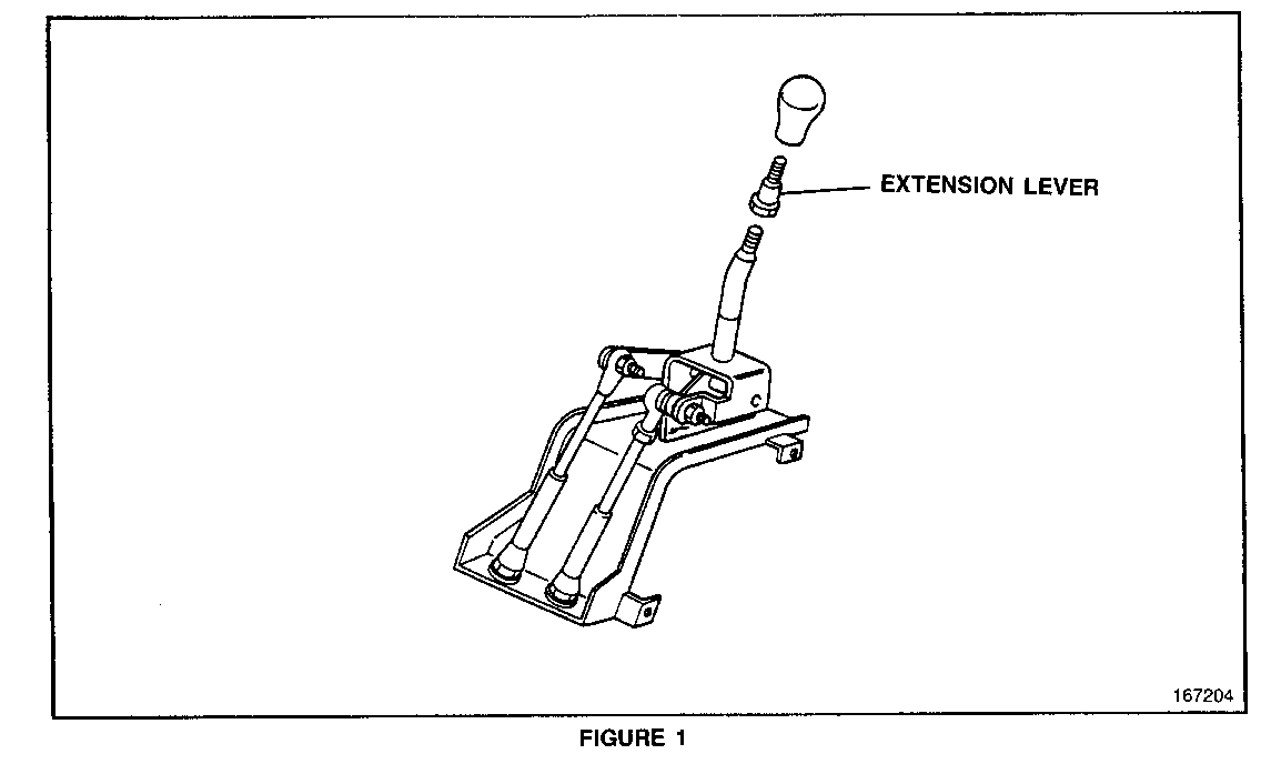
2. Disconnect shift knob from shift lever (figure 1).
3. Connect new extension to shift lever, torque to N.m (33 lbs. ft.).
4. Connect shift knob onto shift lever extension.
5. Tilt cab forward.
6. Disconnect negative (-) battery cable from battery.
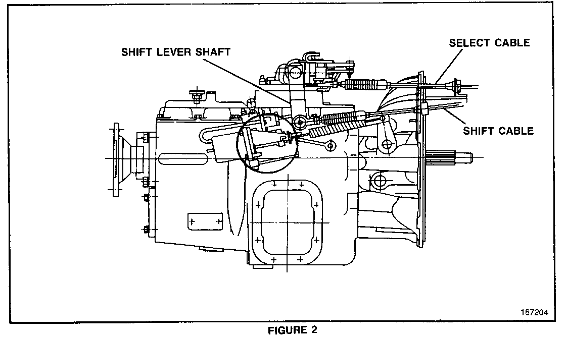
7. Disconnect shift cables from shift levers (figure 2).
8. Disconnect upper shift cover (quadrant box) from lower cover.
9. Disconnect link rod.
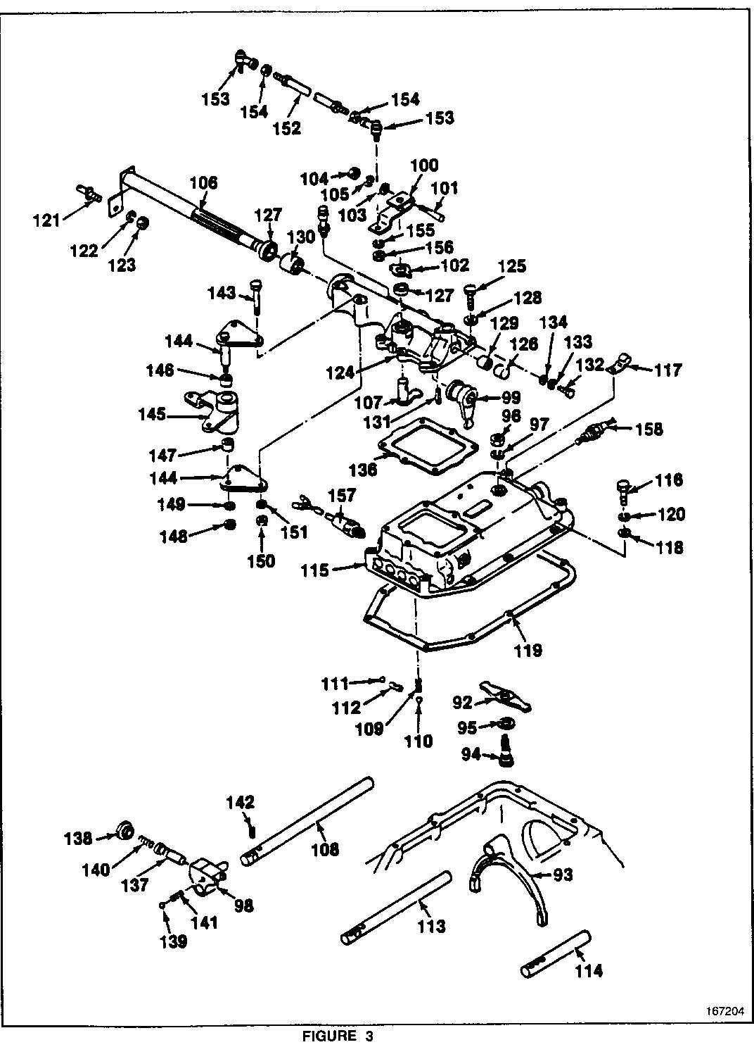
10. Disconnect external selector lever by removing key (wedge) bolt and nut (figure 3).
11. Disconnect washer and oil seal from internal select lever.
12. Disconnect spring pin from shift shaft.
13. Disconnect internal shift lever.
14. Disconnect shift pivot bracket bolts and remove pivot.
15. Discard shift lever/shaft.
16. Connect shift pivot bracket bolts, washer, and nut to new shift lever/shaft.
17. Connect spring pin.
18. Connect internal select lever, oil seal, and washer.
19. Connect new external select lever using existing bolt, nut, and washer.
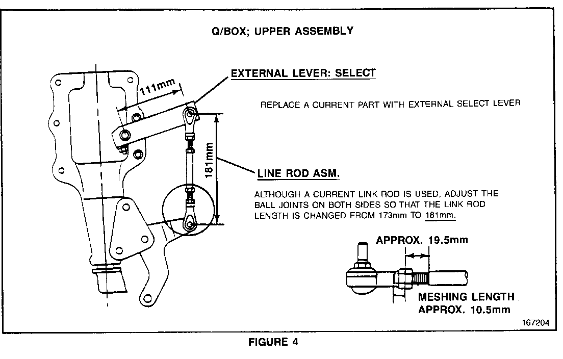
20. Connect link rod and change length from 173 mm to 181 mm (6 11/16 in. to 7 1/8 in.) (figure 4).
21. Connect upper shift cover (quadrant box) to lower cover.
NOTE: The left rear and right front bolts have a thicker neck that serves as dowels for cover alignment.
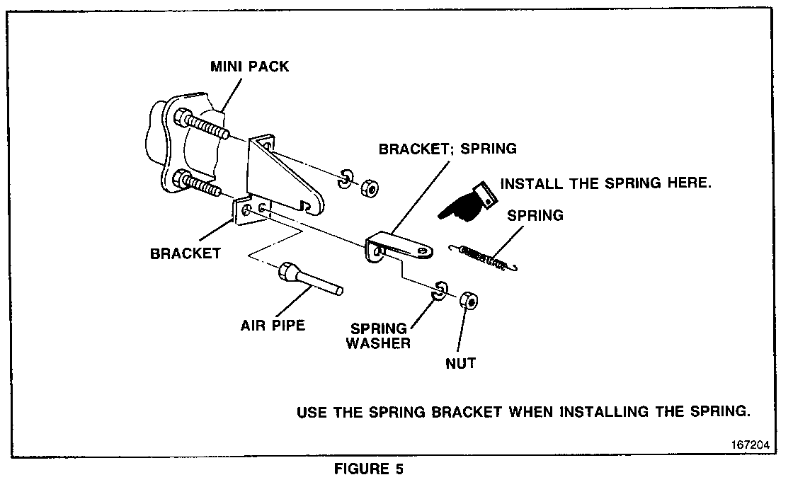
Clutch Mini Pack (Figure 5)
1. Replace bracket, spring bracket, spring, spring washer, and nut.
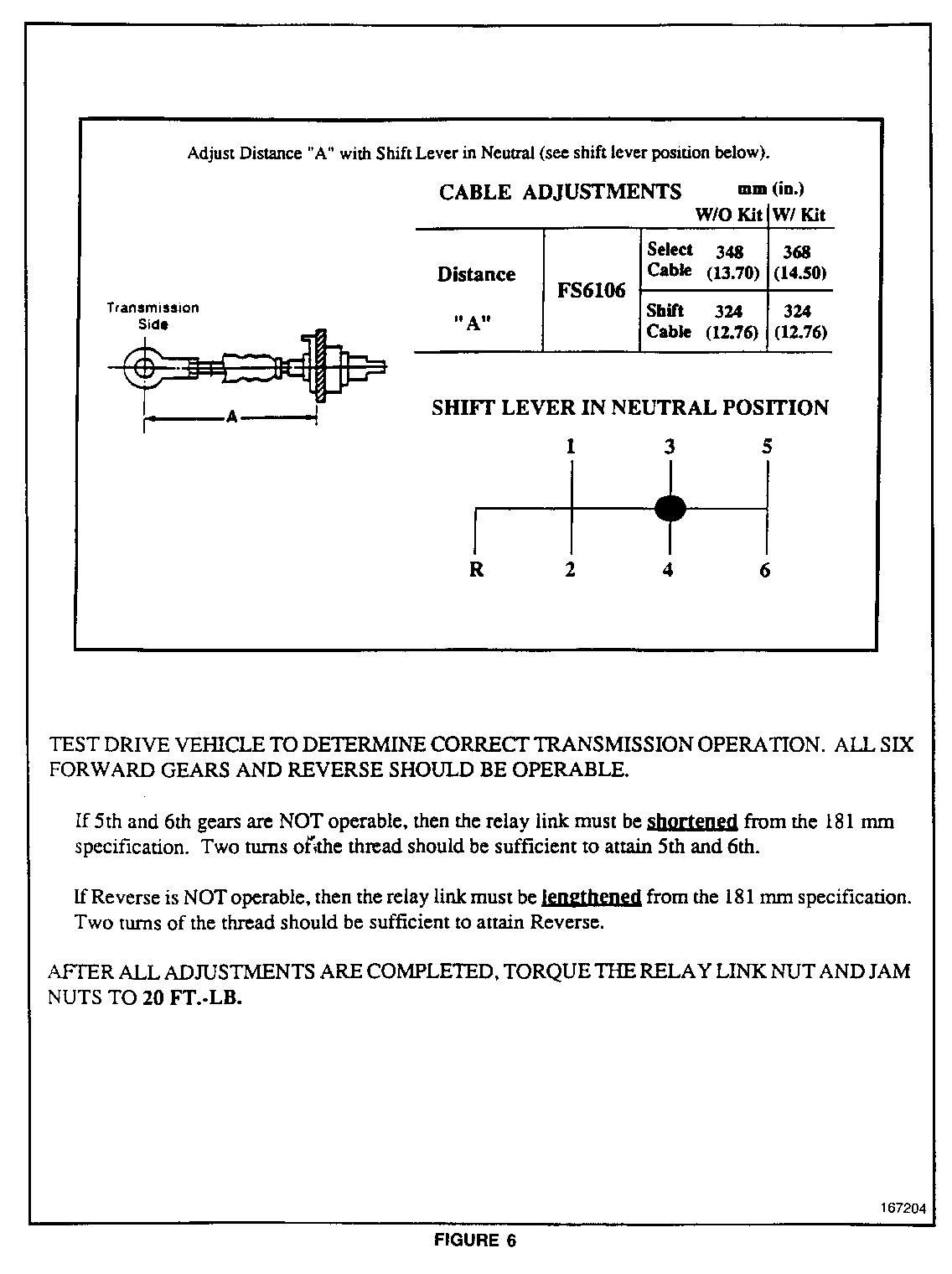
Cable Adjustments (Figure 6)
1. Adjust select cable to 368 mm (14 1/2 in.).
2. Adjust shift cable to 324 mm (12 3/4 in.).
NOTE: After all adjustments are completed, torque relay link nut and jam nut to 26 N.m (20 lbs ft).
3. Connect negative (-) battery cable back to battery.
4. Lower the cab.
5. Remove blocks from rear wheels.
6. Test drive vehicle to determine correct transmission operations. All six forward gears and reverse should be operable.
SERVICE PARTS INFORMATION:
Parts are available through American Isuzu Parts Distribution Network (AIPDN) as a kit.
The kit part number is 94060388. The kit consists of the following components:
Part Number Description Qty. ------ ----------- ---- 94060386 Extension Lever 1 94060384 External Selection 1 94060385 Shift Lever 1 94060383 Spring Bracket 1
WARRANTY INFORMATION:
For vehicles repaired under warranty use:
Labor Operation: K2240
Labor Time: 1.5 hrs.
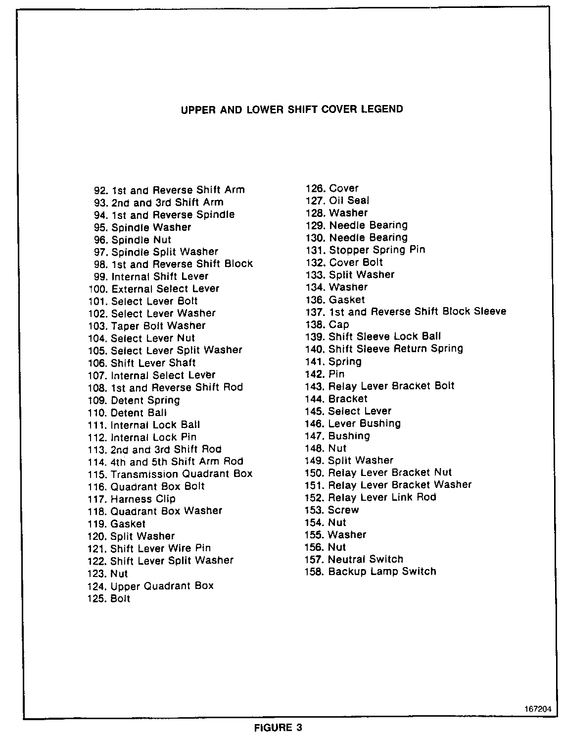
UPPER AND LOWER SHIFT COVER LEGEND
92. 1st and Reverse Shift Arm 126. Cover 93. 2nd and 3rd Shift Arm 127. Oil Seal 94. 1st and Reverse Spindle 128. Washer 95. Spindle Washer 129. Needle Bearing 96. Spindle Nut 130. Needle Bearing 97. Spindle Split Washer 131. Stopper Spring Pin 98. 1st and Reverse Shift Block 132. Cover Bolt 99. Internal Shift Lever 133. Split Washer 100. External Select Lever 134. Washer 101. Select Lever Bolt 136. Gasket 102. Select Lever Washer 137. 1st and Reverse Shift Block Sleeve 103. Taper Bolt Washer 138. Cap 104. Select Lever Nut 139. Shift Sleeve Lock Ball 105. Select Lever Split Washer 140. Shift Sleeve Return Spring 106. Shift Lever Shaft 141. Spring 107. Internal Select Lever 142. Pin 108. 1st and Reverse Shift Rod 143. Relay Lever Bracket Bolt 109. Detent Spring 144. Bracket 110. Detent Ball 145. Select Lever 111. Internal Lock Ball 146. Lever Bushing 112. Internal Lock Pin 147. Bushing 113. 2nd and 3rd Shift Rod 148. Nut 114. 4th and 5th Shift Arm Rod 149. Split Washer 115. Transmission Quadrant Box 150. Relay Lever Bracket Nut 116. Quadrant Box Bolt 151. Relay Lever Bracket Washer 117. Harness Clip 152. Relay Lever Link Rod 118. Quadrant Box Washer 153. Screw 119. Gasket 154. Nut 120. Split Washer 155. Washer 121. Shift Lever Wire Pin 156. Nut 122. Shift Lever Split Washer 157. Neutral Switch 123. Nut 158. Backup Lamp Switch 124. Upper Quadrant Box 125. Bolt
TEST DRIVE VEHICLE TO DETERMINE CORRECT TRANSMISSION OPERATION. ALL SIX FORWARD GEARS AND REVERSE SHOULD BE OPERABLE.
If 5th and 6th gears are NOT operable, then the relay link must be shortened from the 181 mm specification. Two tums of the thread should be sufficient to attain 5th and 6th.
If Reverse is NOT operable, then the relay link must be lengthened from the 181 mm specification. Two tums of the thread should be sufficient to attain Reverse.
AFTER ALL ADJUSTMENTS ARE COMPLETED, TORQUE THE RELAY LINK NUT AND JAM NUTS TO 20 FT.-LB.
General Motors bulletins are intended for use by professional technicians, not a "do-it-yourselfer". They are written to inform those technicians of conditions that may occur on some vehicles, or to provide information that could assist in the proper service of a vehicle. Properly trained technicians have the equipment, tools, safety instructions and know-how to do a job properly and safely. If a condition is described, do not assume that the bulletin applies to your vehicle, or that your vehicle will have that condition. See a General Motors dealer servicing your brand of General Motors vehicle for information on whether your vehicle may benefit from the information.
