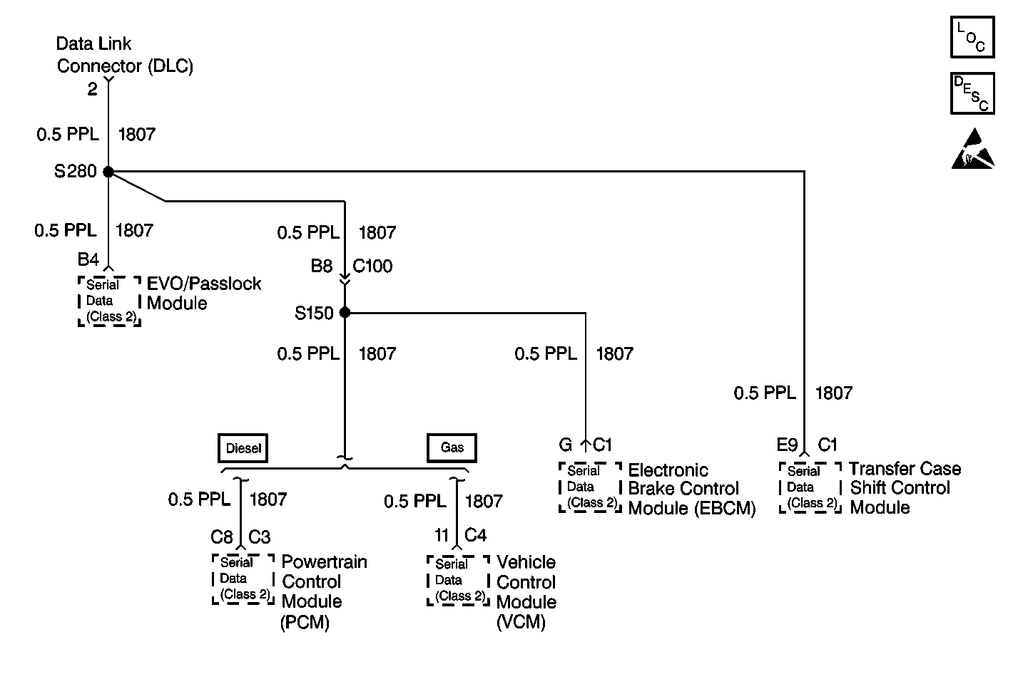
Circuit Description
This circuit supplies the Passlock data to the Vehicle Control Module (VCM)/Powertrain Control Module (PCM) from the Passlock™ Module, as well as communicating all of the Class 2 messages among all of the modules and the tool, CKT 1807 (PPL).
Conditions for Setting the DTC
All of the following conditions must be met:
| • | The ignition is active. |
| • | Communication with the Data Link Connector and other modules is lost or at least has been lost at one time due to intermittent connection (this is usually a DTC). |
Action Taken When the DTC Sets
| • | Stores DTC U1125 in the Passlock™ Module memory. |
| • | If the ignition was OFF at the time, the vehicle will not start again. |
| • | If the engine was running at the time, the vehicle will start again but the SECURITY indicator will remain illuminated. |
Conditions for Clearing the DTC
| • | The Passlock™ Module continuously monitors the signal and moves the DTC from current to history on the next ignition cycle when the condition causing the fault no longer exists. |
| All Passlock™ Module history codes will be cleared after 100 ignition cycles (from OFF to RUN) with no current codes active during the 100 ignition cycles. |
| • | Using a scan tool. |
Diagnostic Aids
| • | When the diagnostics direct you to take electrical measurements at the Wiring Harness Junction Blocks, refer to Wiring Systems for terminal assignments of the Wiring Harness Junction Blocks. |
| • | If the DTC is a history DTC, the problem may be intermittent. Try performing the test shown while wiggling wiring and connectors, this can often cause the malfunction to appear. |
Test Description
The number(s) below refer to the step number(s) on the diagnostic table.
-
The VTD Diagnostic System Check will test the scan tool's ability to communicate with the EVO/Passlock Module and the Vehicle Control Module VCM/PowertrainControl Module (PCM). If communications are unable to be establishedwith either module a CURRENT fault exists. This fault could be causedbya faulty power or ground circuit to the affected module, a faulty CKT 1807 (PPL), or a faulty control module. The VTD Diagnostic System Check table willdetermineif power or ground circuits are faulty. If the power and groundstest OK, you are referred to Diagnostic System Check - Data Link Communications to diagnose CKT 1807 (PPL)or a faulty EVO/Passlock Module.
-
This step is to determine if the scan tool can use CKT 1807 (PPL) to communicate with the VCM/PCM.
-
This step is to determine the problem with CKT 1807 (PPL). Whetherit is fault of the circuit or fault of the Passlock™ Module.
-
In this step be sure to connect all connectors removed during the diagnosisand perform the reprogramming of the Passlock™ Module.
Step | Action | Value(s) | Yes | No |
|---|---|---|---|---|
Was the VTD Diagnostic System Check performed? | -- | Go to Step 2 | Go to Diagnostic System check in Theft Deterrent | |
Does the scan tool communicate with the VCM/PCM? | -- | Go to Step 3 | ||
Is the resistance below the specified value? | 0-5ohms | Go to Step 4 | Go to Step 5 | |
Replace the Passlock™ Module. Is the repair complete? | -- | -- | ||
5 | Locate and repair the open or cause of resistance in CKT 1807 (PPL) between the Passlock™ Module and the DLC. Refer to Wiring Repairs in Wiring Systems. Is the repair complete? | -- | -- |
