Customer Satisfaction - Trans Control Module Logic Error

| Subject: | 0075 -- Trans Control Module Logic Error |
| Models: | 1999-2000 Chevrolet and GMC W3500/4500/5500 Series Vehicles |
Condition
Some 1999-2000 Chevrolet and GMC W3500/4500/5500 series vehicles may exhibit a condition where the Transmission Control Module (TCM) may exhibit a logic error. This TCM logic error can, under certain operating conditions, prevent transmission torque converter lockup and lessen the exhaust brake effectiveness; however, the exhaust brake effectiveness is still within the requirements of FMVSS 102 for transmission braking. If the vehicle is driven at sustained highway speeds for prolonged periods of time without the torque converter in the lock up mode, the transmission fluid sump temperatures may rise. If this were to occur, it could result in damage to the front pump seal.
Correction
Dealers are to install an extension harness.
Vehicles Involved
Involved are certain 1999-2000 Chevrolet and GMC W3500/4500/5500 series vehicles built within these VIN breakpoints:
Year | Division | Model | Plant | From | Through |
|---|---|---|---|---|---|
1999 | GMC | W3500/4500 | Fujisawa | X7000004 | X7021118 |
1999 | GMC | W5500 | Fujisawa | X7900009 | X7906146 |
2000 | GMC | W3500/4500 | Fujisawa | Y7000005 | Y7009641 |
2000 | GMC | W5500 | Fujisawa | Y7900014 | Y7901379 |
1999 | Chevrolet | W3500/4500 | Fujisawa | X7000477 | X7021107 |
1999 | Chevrolet | W5500 | Fujisawa | X7900104 | X7906171 |
2000 | Chevrolet | W3500/4500 | Fujisawa | Y7000041 | Y7009646 |
2000 | Chevrolet | W5500 | Fujisawa | Y7900116 | Y7901344 |
Important: Dealers should confirm vehicle eligibility through GMVIS (GM Vehicle Inquiry System) prior to beginning campaign repairs. [Not all vehicles within the above breakpoints may be involved.]
Involved vehicles have been identified by Vehicle Identification Number. Computer listings containing the complete Vehicle Identification Number, customer name and address data have been prepared, and are being furnished to involved dealers with the campaign bulletin. The customer name and address data furnished will enable dealers to follow up with customers involved in this campaign. Any dealer not receiving a computer listing with the campaign bulletin has no involved vehicles currently assigned.
These dealer listings may contain customer names and addresses obtained from Motor Vehicle Registration Records. The use of such motor vehicle registration data for any other purpose is a violation of law in several states/provinces/countries. Accordingly, you are urged to limit the use of this listing to the follow-up necessary to complete this campaign.
Parts Information
Parts required to complete this campaign are to be obtained from General Motors Service Parts Operations (GMSPO). Please refer to your "involved vehicles listing" before ordering requirements. Normal orders should be placed on a DRO = Daily Replenishment Order. In an emergency situation, parts should be ordered on a CSO = Customer Special Order.
Part Number | Description | Qty/ Vehicle |
|---|---|---|
97228337 | Cable, A/Trns Range Sel Lvr | 1 |
94259851 | Relay, Trns Wiring Harness | 1 |
94024490 | Clip, Wrg Harn | 1 |
Service Procedure
- Disconnect the negative battery cable.
- Install the relay to the extension harness and attach the bracket of the relay to the TCM mounting stud using the existing nut (Figure 1).
- Disconnect the 26-pin and 16-pin connectors of the TCM.
- With the 16-pin connector terminal end facing away and the lock tab facing up, connect the tap of SB28 (LT GRN) to the TCM harness wire SB28 (LT GRN), located at the top row, right end of the connector (Figure 2, Item 1).
- At the junction point of the tap (RED), cut the original wire leading to the vehicle so that the tap connects only SB28 wire from the 16-pin connector to the new SB28 (LT GRN) from the extension harness.
- Tape the cut wire to the branch of the harness to protect it from grounding.
- With the 16-pin connector terminal end facing away and the lock tab facing up, connect the tap of OA74 (LT GRN/WHT stripe) to the TCM harness wire OA74 (LT GRN/WHITE stripe) located at the fourth pin from the right of the bottom row (Figure 2, Item 2).
- At the junction point of the tap (RED), cut the original wire leading to the vehicle so that the tap connects only OA74 wire from the 16-pin connector to the new OA74 (LT GRN/WHT stripe) from the extension harness.
- Tape the cut wire to the branch of the harness to protect it from grounding.
- With the 26-pin connector terminal end facing away and the lock tab facing up, connect the tap of OA75 (BLK/MAROON stripe) to the TCM harness wire OA75 (BLK/MAROON stripe), located at the fourth pin from the left of the bottom row. DO NOT CUT ANY WIRE AT THIS HARNESS JUNCTION (Figures 3 and 4).
- Using a multi-meter in continuity check mode, test for continuity between the following connections:
- Using a multi-meter set to the diode's range, measure the diode voltage (Figure 7).
- When all the connectors are completed and tested, reconnect the 16-pin and 26-pin connectors to the TCM. If the third connector to the TCM was disconnected previously, be sure that it is reconnected at this time.
- Remove the cover underneath the dash along the center and passenger side and place it in a safe location (Figure 8).
- Remove the two nuts (M8) mounted to the pedal bracket assembly and pull the pedal assembly out as much as possible for accessibility (Figures 9 and 10).
- Disconnect the two cables attached to the accelerator pedal in four places.
- Partially remove the pedal assembly and disconnect the (BLK) kick-down switch connector (w/BLK and GRY wire), then disconnect the acceleration switch connector (BLK).
- Locate and expose the existing 4-pin connector (BLK) that is taped to the vehicle harness. This connector is located directly above the pedal assembly, bundled to the main vehicle harness by electrical tape (Figure 11).
- Route the extension harness over the TCM and brake master cylinder to above the accelerator pedal assembly.
- Connect the 4-pin extension connector (BLK w/single LT GRN wire) to the 4-pin connector (BLK) that was previously taped to the main vehicle harness (Figure 12).
- Connect the female 2-pin extension connector (WHT) to the male 2-pin vehicle harness connector (BLK w/2 LT GRN wires) (Figure 13).
- Connect the male 2-pin extension connector (WHT) to the female 2-pin acceleration switch connector (BLK w/RED and BLK wires) (Figure 14).
- Reattach the two cables to the accelerator pedal assembly.
- Reinstall the pedal bracket assembly and refasten the two (M8) nuts, then reconnect the kick-down switch (Figure 9 and 10).
- Bundle the slack of the extension harness on the left side of the TCM and attach it to the left side of the clutch pedal mounting bracket (not used) with a clip band (Figure 15).
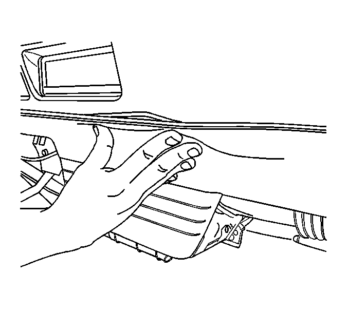
- Reinstall the finishing panel underneath the dashboard on the passenger side (Figure 16).
- Reconnect the negative battery and reset the radio presets and clock, if equipped.
- With the Tech 2 connected, turn the starter key to ON and the Tech 2 power on. Toggle through the menu to enter AISIN TCM diagnostics, and clear the existing transmission DTC information.
- With the Tech 2 connected, conduct a road test using the displayed data list from the Tech 2 to verify:
- After the road test, confirm that no TCM DTC is displayed, using the Tech 2.
- Turn the Tech 2 unit off and disconnect it from the vehicle.
- Install the GM Campaign Identification Label.
Figure 1
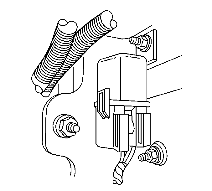
Figure 2
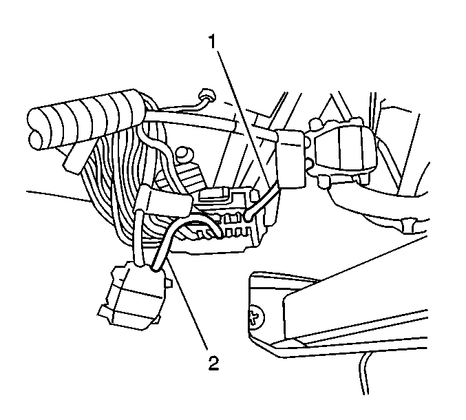
Figure 3
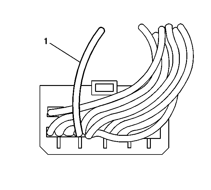
Figure 4
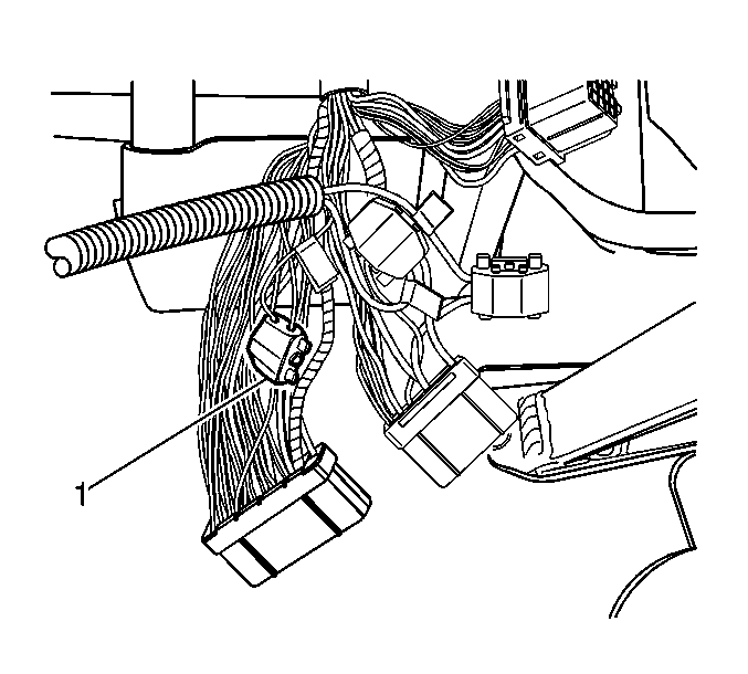
Important: Do not cut any wire at the harness junction in the next step.
Important: The black 4-pin connector has only one wire in the connector.
Figure 5
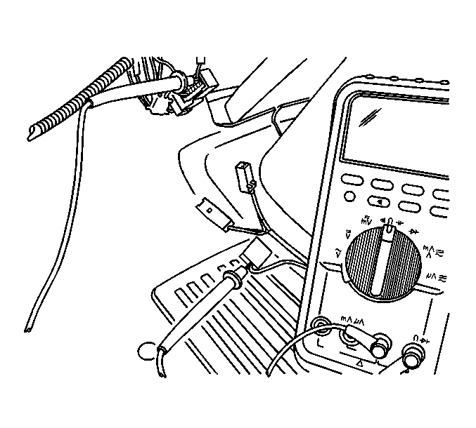
| - | Between SB28 (LT GRN) at the TCM 16-pin connector terminal and SB28 (LT GRN) at the extension harness 4-pin female connector (BLK) (Figure 5). |
Figure 6
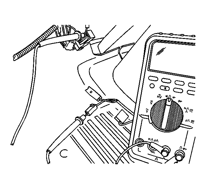
| - | Between OA74 (LT GRN/WHT stripe) at the TCM 16-pin connector terminal and SB29 (LT GRN/WHT stripe) at the extension harness 2-pin male connector (WHT) (Figure 6). |
Figure 7
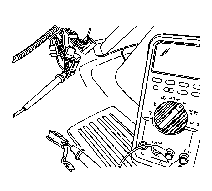
| - | Connect the negative side of the probe to OA75 (BLK/MAROON stripe) at the TCM 26-pin connector terminal. |
| - | Connect the positive side of the probe to SB29 (WHT) at the extension harness 2-pin female connector (WHT). |
| - | The displayed value should be in the range of approximately 0.3 to 0.6 volts. |
Figure 8
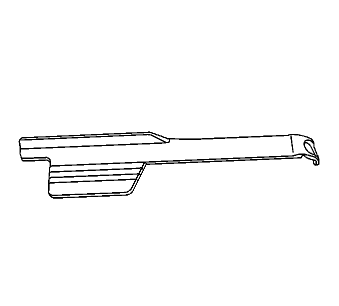
Figure 9
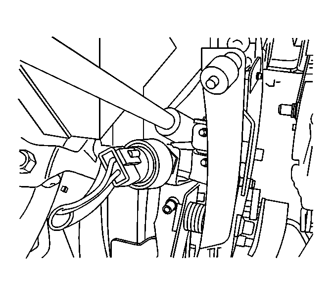
Figure 10
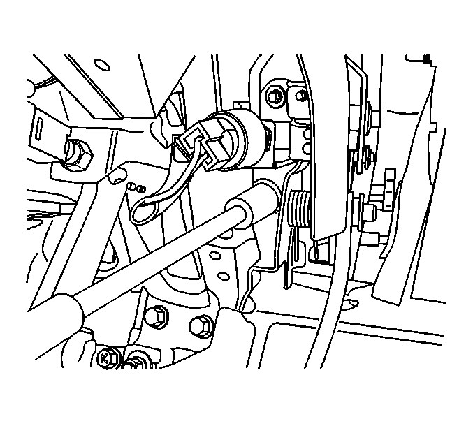
Figure 11
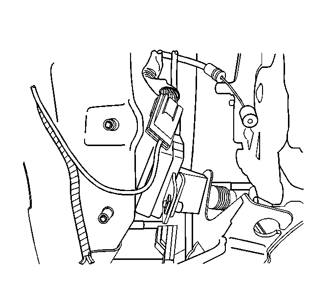
Figure 12
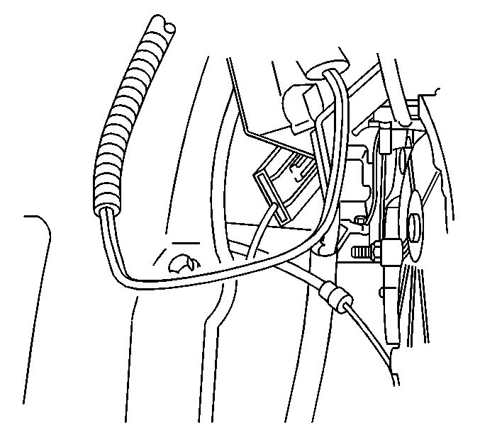
Figure 13
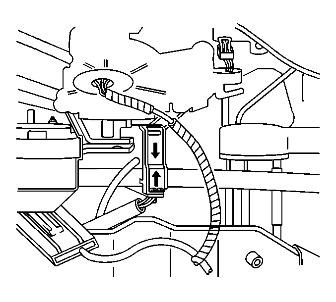
Figure 14
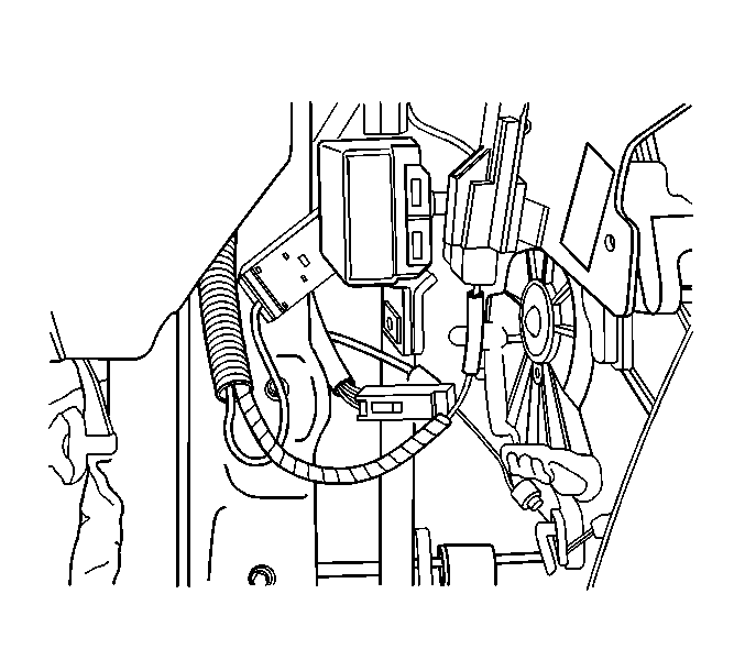
Figure 15
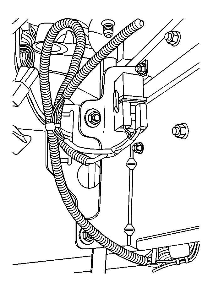
Important: Be sure than the harnesses near the pedal bracket assembly are not pinched during the next step.
Figure 16
| - | Does the TCM data list the kick-down switch signal while accelerating at wide-open throttle? |
| - | With the selector switch in Overdrive and accelerating to speed, does torque converter lock-up occur in 3rd and 4th gear (as displayed in the Tech 2 data list)? |
| - | By toggling the exhaust brake lever switch during deceleration, can you hear the exhaust brake activating along with the displayed signal in the Tech 2 data list (EXH B SW & EXH, B RELAY)? |
Campaign Identification Label
Place a Campaign Identification Label on each vehicle corrected in accordance with the instructions outlined in this Product Campaign Bulletin. Each label provides a space to include the campaign number and the five (5) digit dealer code of the dealer performing the campaign service. This information may be inserted with a typewriter or a ball point pen.
Put the Campaign Identification Label on a clean and dry surface of the radiator core support in an area that will be visible to people servicing the vehicle. When installing the Campaign Identification Label, be sure to pull the tab to allow the adhesion of the clear protective covering. Additional Campaign Identification Labels for US dealers can be obtained from Dealer Support Materials by calling 1-888-549-6152 (Monday-Friday, 8:00 am to 5:00 pm EST). Ask for Item Number S-1015 when ordering.
Claim Information
Submit a Product Campaign Claim with the information indicated below.
Repair Performed | Part Count | Part No. | Parts Allow | CC-FC | Labor Op | Labor Hours* |
|---|---|---|---|---|---|---|
Install Aisin Extension Harness | 3 | -- | ** | MA-96 | V0579 | 0.7 |
* -- For Campaign Administrative Allowance, add 0.1 hours to the "Labor Hours". ** -- The "Parts Allowance" should be the sum total of the current GMSPO Dealer Net price plus applicable Mark-Up for the parts needed to complete the repair. | ||||||
Refer to the General Motors WINS Claim Processing Manual for details on Product Campaign Claim Submission.
Customer Notification
Customers will be notified of this campaign on their vehicles by General Motors (see copy of customer letter included with this bulletin).
Dealer Campaign Responsibility
All unsold new vehicles in dealers' possession and subject to this campaign MUST be held and inspected/repaired per the service procedure of this campaign bulletin BEFORE customers take possession of these vehicles.
Dealers are to service all vehicles subject to this campaign at no charge to customers, regardless of mileage, age of vehicle, or ownership, from this time forward.
Customers who have recently purchased vehicles sold from your vehicle inventory, and for which there is no customer information indicated on the dealer listing, are to be contacted by the dealer. Arrangements are to be made to make the required correction according to the instructions contained in this bulletin. This could be done by mailing to such customers a copy of the customer letter accompanying this bulletin. Campaign follow-up cards should not be used for this purpose, since the customer may not as yet have received the notification letter.
In summary, whenever a vehicle subject to this campaign enters your vehicle inventory, or is in your dealership for service in the future, you must take the steps necessary to be sure the campaign correction has been made before selling or releasing the vehicle.
October, 2000Dear Chevrolet/GMC Customer:
This notice is sent to inform you of a recall campaign that includes your vehicle.
Reason For This Recall
Some 1999-2000 Chevrolet and GMC W3500/4500/5500 series vehicles may exhibit a condition where the Transmission Control Module (TCM) may exhibit a logic error. This TCM logic error can, under certain operating conditions, prevent transmission torque converter lockup and lessen the exhaust brake effectiveness; however, the exhaust brake effectiveness is still within the requirements of FMVSS 102 for transmission braking. If the vehicle is driven at sustained highway speeds for prolonged periods of time without the torque converter in the lock up mode, the transmission fluid sump temperatures may rise. If this were to occur, it could result in damage to the front pump seal.
What Will Be Done
Your Chevrolet/GMC dealer will install an extension harness. This service will be performed for you at no charge .
Contacting Your Dealer
Please contact your Chevrolet/GMC dealer as soon as possible to arrange a service date and to assure parts availability. Instructions for making this correction have been sent to your dealer. Please ask your dealer if you wish to know how much time will be needed to schedule, process, and repair your vehicle.
If you experience any trouble scheduling your vehicle or you have any questions regarding this recall action, please contact the appropriate Customer Assistance Center at the number listed below:
Division | Number | Deaf, Hearing Impaired, or Speech Impaired* |
|---|---|---|
Chevrolet | 1-800-222-1020 | 1-800-833-2438 |
GMC | 1-800-462-8782 | 1-800-462-8583 |
* Utilizes Telecommunication Devices for the Deaf/Text Telephones (TDD/TTY) | ||
Customer Reply Card
The enclosed customer reply card identifies your vehicle. Presentation of this card to your dealer will assist in making the necessary correction in the shortest possible time. If you no longer own this vehicle, please let us know by completing the card and returning it to us in the postage paid envelope.
We are sorry to cause you this inconvenience; however, we have taken this action in the interest of your continued satisfaction with our products.
Chevrolet/Pontiac-GMC Division
General Motors Corporation
Enclosure
