Customer Satisfaction - Fuel Injection Pump Timing Gear Fracture

| Subject: | 98048 -- Fuel Injection Pump Timing Gear Fracture |
| Models: | 1999 Chevrolet and GMC W4 and W5 Diesel Vehicles |
General Motors has decided that certain 1999 Chevrolet and GMC W4 and W5 diesel vehicles may exhibit a condition in which the injection pump gear may contain a machining burr on the gear surface. This condition may cause the injection pump timing gear to break, resulting in possible engine damage.
To prevent the possibility of this condition occurring, dealers are to replace the injection pump timing gear.
Vehicles Involved
Involved are certain 1999 Chevrolet and GMC W4 and W5 diesel vehicles built within the following VIN breakpoints:
Year | Division | Model | Plant | Plant Code | From | Through |
|---|---|---|---|---|---|---|
1999 | Chevrolet | W4 | Fujisawa | 7 | X7000006 | X7006499 |
1999 | Chevrolet | W5 | Fujisawa | 7 | X7900104 | X7901537 |
1999 | GMC | W4 | Fujisawa | 7 | X7000014 | X7006197 |
1999 | GMC | W5 | Fujisawa | 7 | X7900009 | X7901516 |
Important: Dealers should confirm vehicle eligibility through VISS (Vehicle Information Service System) or ServiceNet (GMC only) prior to beginning campaign repairs. [Not all vehicles within the above breakpoints may be involved.]
Involved vehicles have been identified by Vehicle Identification Number. Computer listings containing the complete Vehicle Identification Number, customer name and address data have been prepared, and are being furnished to involved dealers with the campaign bulletin. The customer name and address data furnished will enable dealers to follow-up with customers involved in this campaign. Any dealer not receiving a computer listing with the campaign bulletin has no involved vehicles currently assigned.
These dealer listings may contain customer names and addresses obtained from State Motor Vehicle Registration Records. The use of such motor vehicle registration data for any other purpose is a violation of law in several states. Accordingly, you are urged to limit the use of this listing to the follow-up necessary to complete this campaign.
Parts Information
Important: The special tool kit required for this campaign will be pre-shipped to dealers. This pre-shipment will begin the week of October 19, 1998. The special tool kit will arrive directly from Isuzu.
Parts required to complete this campaign (except the special tool kit) are to be obtained from General Motors Service Parts Operations (GMSPO). Please refer to your "involved vehicles listing" prior to ordering requirements. Normal orders should be placed on a DRO = Daily Replenishment Order. An emergency requirement should be ordered on a CSO = Customer Special Order.
Part Number | Description | Qty/ Vehicle |
|---|---|---|
97211705 | Injection Pump Gear | 1 |
Part Number | Description | Qty/ Vehicle |
|---|---|---|
94034146 | Small Fiber Gasket | 1 |
97039200 | Large Pump to Flywheel Housing O-Ring | 1 ` |
94000374 | Small Copper Gasket | 1 |
94036238 | Orange Dipstick Tube O-Ring | 1 |
94000490 | Coated Gasket | 1 |
94315436 | Injection Pump Harness Clip | 1 |
940341481 | Fuel Pipe Gasket | 1 |
*Spare Parts - These parts may be necessary to complete the replacement in isolated cases . These parts will not need to be replaced in every gear replacement.
Part Number | Description | Comments |
|---|---|---|
NPN | Injection Pump Gear Holder | These tools are to be used when installing the Injection Pump Gear |
Gear Holder Bolt & Nut | ||
Quality Check Tool |
Customer Notification
Customers will be notified of this campaign on their vehicles by General Motors (see copy of typical customer letter included with this bulletin - actual divisional letter may vary slightly).
Dealer Campaign Responsibility
All unsold new vehicles in dealers' possession and subject to this campaign MUST be held and inspected/repaired per the service procedure of this campaign bulletin BEFORE customers take possession of these vehicles.
Dealers are to service all vehicles subject to this campaign at no charge to customers, regardless of mileage, age of vehicle, or ownership, from this time forward.
Customers who have recently purchased vehicles sold from your vehicle inventory, and for which there is no customer information indicated on the dealer listing, are to be contacted by the dealer. Arrangements are to be made to make the required correction according to the instructions contained in this bulletin. This could be done by mailing to such customers a copy of the customer letter accompanying this bulletin. Campaign follow-up cards should not be used for this purpose, since the customer may not as yet have received the notification letter.
In summary, whenever a vehicle subject to this campaign enters your vehicle inventory, or is in your dealership for service in the future, please take the steps necessary to be sure the campaign correction has been made before selling or releasing the vehicle.
Special Tool
During the week of October 19, 1998, each dealer will be shipped a special tool kit from AIPDN for use in this campaign. This tool is being furnished at no charge.
Service Procedure
Removal Procedure
- Before tilting the cab, rotate the idle control knob at the dash panel to "minimum" position (counterclockwise)
- Disconnect the battery ground cable.
Figure 1
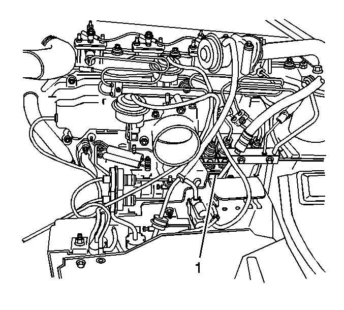
Injection Pump Timing Gear Replacement
- Turn the injection pump gear until the mark on the gear lines up with the 11 o'clock bolt hole. Refer to Figure 20.
- Install the gear holder with the included mounting fasteners. Refer to Figures 21 and 22.
- Remove the six (6) 14mm bolts.
- Remove and discard the old gear.
- Install the new gear with the alignment mark near the 11 o'clock bolt hole. Refer to Figure 20.
- Install the six (6) 14mm bolts to the gear. Refer to Figure 22.
- Tighten the six (6) 14mm bolts. Refer to Figure 23
- Remove the fasteners securing the gear holding tool and remove the tool.
Figure 20
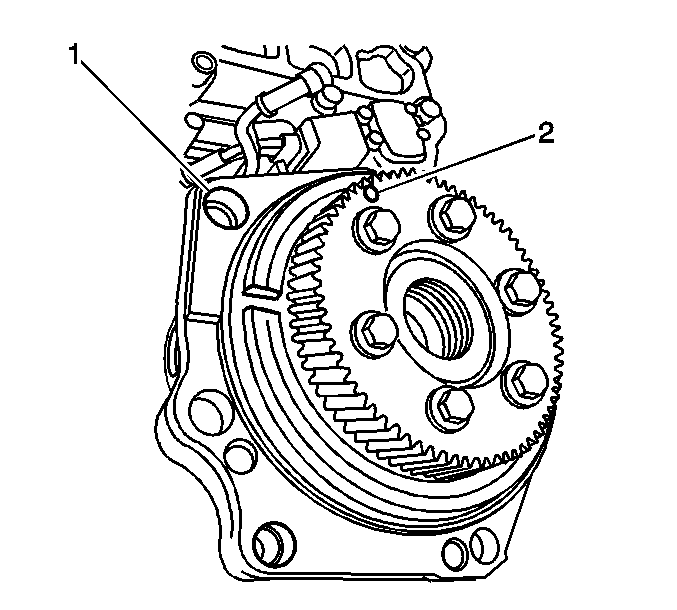
| (1) | 11 o'clock bolt hole |
| (2) | Align mark |
Figure 21
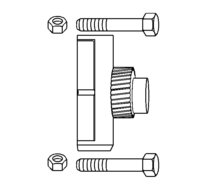
Figure 22
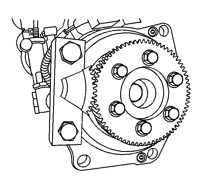
Figure 23
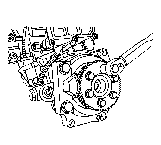
Tighten
Tighten the bolts to 34 N·m (25 lb ft).
Installation Procedure
- Align the injection pump timing mark with the timer slit. Refer to Figure 24.
- Install the replacement injection pump assembly.
- After mounting, make sure that the "13 degree" mark is in position through the injection pump timing inspection hole. Refer to Figure 3.
- Reinstall the bottom injection pump bracket.
- Turn the crankshaft until the timing mark on the crankshaft damper pulley is aligned with the "8 degrees" BTDC. Refer to Figure 2.
- Confirm that the "8 degree" mark comes to position in the injection pump timing inspection hole. Refer to Figure 3.
- Reinstall the timing inspection plug.
- Reconnect the MI-TICS harness.
- Reinstall the intake plenum.
- Insert the bottom half of the blue injection line fixing clamps on the threaded mounting studs.
- Reinstall the fuel injection line assembly and hand tighten the injection pipe sleeve nuts.
- Reinstall the top half of the injection line fixing clamps.
- Tighten the injection pipe sleeve nuts.
- Reinstall the return hose to the PCV breather canister. Refer to Figure 26.
- Reinstall the injection pump oil supply line. Refer to Figures 27 and 27A.
- Reinstall the fuel filter assembly. Refer to Figure 28
- Reinstall the two fuel line bracket attachment bolts near the serial data plate of the injection pump.
- Position the fuel return line in place and reinstall the check-valved banjo bolt. Refer to Figures 27A and 29.
- Place two fuel line banjo bolts side-by-side as shown in Figure 30.
- Position the fuel line that leads from the feed pump to the fuel filter assembly and reinstall bolt A (smaller center passage) with sealing washers. Refer to Figure 27A and 31
- Position the fuel line that leads from the fuel filter assembly to the injection pump and reinstall bolt B (larger center passage) with sealing washers. Refer to Figures 27A and 32.
- Reinstall the mounting bracket for the line fixing clamps.
- Reinstall the L shaped inlet line at the feed pump. Make sure there is a white plastic filtering screen inside this banjo bolt. Refer to Figures 27A and 33.
- Reinstall the fuel line fixing clamps. Refer to Figure 33.
- Reconnect the fuel feed hose.
- Reconnect the fuel return hose.
- Reinstall the engine speed sensor and reconnect the harness.
- Reinstall the dipstick tube.
- Reinstall the throttle lever assembly and the cables.
- Reinstall the engine stop cable.
- *Automatic Transmission Only (Aisin 450-43LE)
- Reinstall the vacuum control panel and reconnect the control harness.
- Reinstall the intake air duct.
- Reconnect the battery ground cable.
- Perform the following Bleeding the Fuel System Procedure.
Figure 24
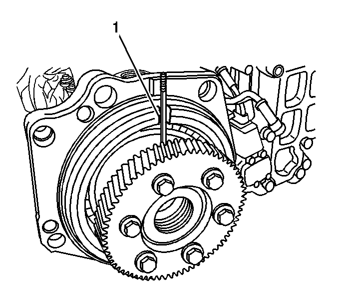
| (1) | Align the timing slits |
Use a suitable tool to accurately align the two marks before installing the pump unit.
Tighten
| • | Tighten the 14mm injection pump mounting fasteners to 48 N·m (35 lb ft). |
| • | Tighten the 17mm injection pump mounting fasteners to 72 N·m (53 lb ft). |
Tighten
Tighten the fasteners to 28 N·m (20 lb ft).
| • | Be sure to reattach the support clip of the bracket to the harness connector. |
| • | The wire harness hold-down tab from the old pump unit must be reused. |
Tighten
Tighten the mounting fasteners to 20 N·m (15 lb ft).
Figure 25 (do not remove fixing clamps 4, 5 and 6)
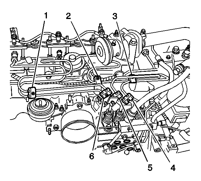
Notice: Make sure that the clamps are in their correct position. Improper placement will result in injection line breakage and fuel pulsing noise. Refer to Figure 25.
Important: There are several wire harness hold-down tabs that must be secured with the mounting bolts.
Tighten
Tighten the mounting nuts to 3 N·m (26 lb in).
Tighten
Tighten the nuts to 29 N·m (22 lb ft).
Figure 26

| (1) | PCV Breather Return Line |
Figure 27

| (1) | Reinstall these banjo bolts |
Figure 27A (Placement of banjo bolts and washers in relation to fuel and oil lines)
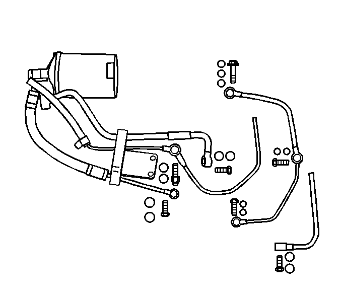
Tighten
Tighten the banjo bolts to 14 N·m (10 lb ft).
Figure 28
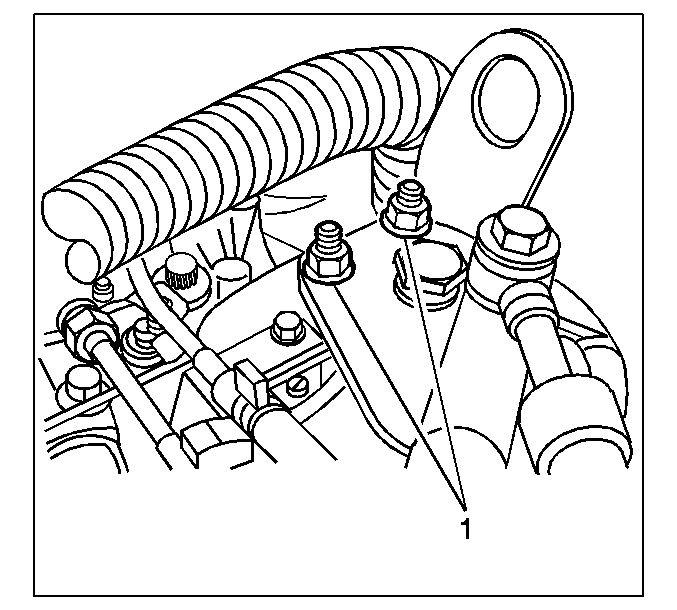
| (1) | Tighten to 34 N·m (25 lb ft). |
Important: To prevent bending of the oil supply line, do not apply excessive force to the injection pump oil supply line.
Tighten
Tighten the bracket bolts to 34 N·m (25 lb ft).
Tighten
Tighten the bracket bolts to 17 N·m (12 lb ft).
Figure 29
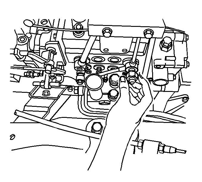
Tighten
Tighten the bolt to 23 N·m (17 lb ft).
Figure 30
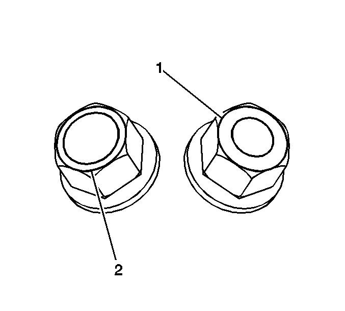
| (1) | Small Hole: Banjo Bolt A to the Feed Pump |
| (2) | Large Hole: Banjo Bolt B to the Injection Pump |
Important: These banjo bolts must be in their proper position.
Figure 31
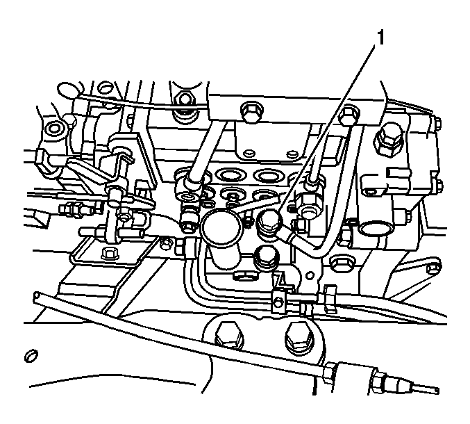
| (1) | Install Bolt A here |
Tighten
Tighten the bolt to 23 N·m (17 lb ft).
Figure 32
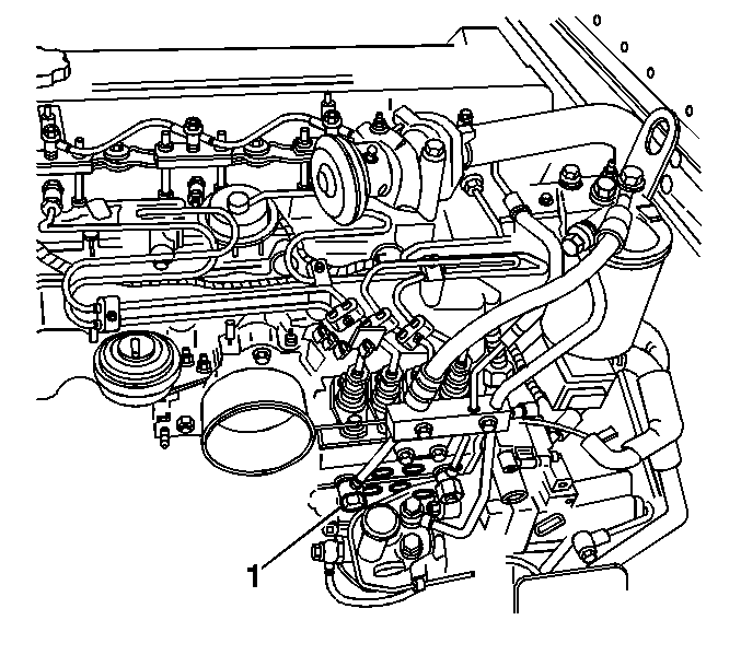
| (1) | Install Bolt B here |
Tighten
Tighten the bolts to 23 N·m (17 lb ft).
Figure 33
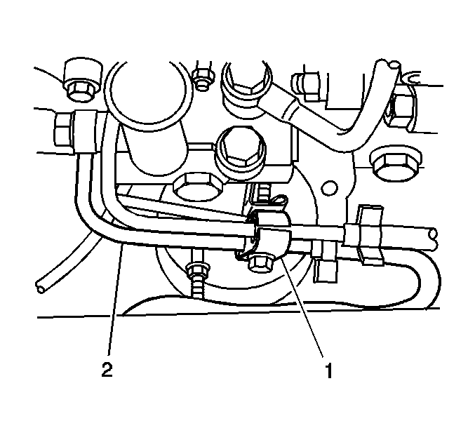
| (1) | Place clamp in its original position |
| (2) | L Shaped Inlet Line |
Tighten
Tighten the banjo bolts to 41 N·m (30 lb ft).
Be sure to remove any plugs.
Tighten
Tighten the engine speed sensor mounting bolt to 5 N·m
(48 lb in).
Important: Reinstall the two orange O-rings before insertion into the engine block.
Verify that the dipstick tube is completely inserted into the engine block. Make sure the attachment bolts are at the proper position and tighten to 13 N·m (113 lb in).Tighten
| • | Tighten the attachment bolts to 19 N·m (14 lb ft). |
| • | Tighten the remaining attachment bolts of the dipstick tube to 13Overdrive N·m (113 lb in). |
Reinstall the automatic transmission fluid filler tube fixing bolt.
Tighten
Tighten the bolt to 13 N·m (113 lb fin).
Figure 34
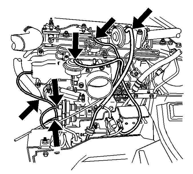
Important: Be sure to reconnect the vacuum hoses to their original position. Improper position may lead to driveability problems. Refer to Figure 34.
Tighten
Tighten the chassis attachment bolts to 19 N·m (14 lb ft).
Tighten
Tighten the intake hose clamps to 6.5 N·m (75.5 lb in).
Figure 35
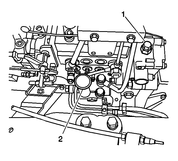
| (1) | Bleed Screw |
| (2) | Primer Pump Knob (twist to release) |
Bleeding the Fuel System
Whenever the fuel system is opened to the atmosphere, outside air can enter. Trapped air in the fuel system will cause the engine to run poorly. After performing any service that requires the opening of the fuel system, all trapped air must be removed by bleeding the fuel system. Refer to Figure 35.
- Loosen the bleed screw on the injection pump.
- Pump the primer pump until the fuel flow is free of air bubbles from the bleed screw.
- Tighten the bleed screw and close the primer pump knob.
- Start the engine and check for any leaks during operation, correct as required.
| • | Twist the pump knob to release the primer pump knob. Push down and twist to close the knob. |
| • | Some fuel may flow out after all the trapped air has escaped. |
Quality Audit Check
In addition to the replacement of the gear and reinstallation of the pump, the technician MUST perform the Quality Audit Check that follows.
TPS Relearn Procedure
Upon completion of the Quality Audit Check, perform the TPS Relearn Procedure.
QUALITY AUDIT CHECK SHEET TICS PUMP CHANGEOUT | |
|---|---|
VIN (last 8 digits): | Date: |
Insp By (technician: | |
PLEASE PERFORM THIS AUDIT IN THE FOLLOWING SEQUENCE: | |
1_______Start engine for warmup, during this time, at idle, monitor the exhaust brake operation to make sure it is closed for the initial warmup. | |
2_______Perform an overall visual inspection. | |
3_______Check for installation of tamper cap on the high RPM adjustment screw. Turn 1/4 turn to lock. Paint cap (if cap is not installed) | |
4_______Check pump numbers for correct pump installed, i.e.: 8972100500______________________For auto & MT 6 speed 8972100510______________________For MT 5 speed Zexel Serial #__________________________________(3rd # down) | |
5_______Check pump mount bolts for torque. Paint (5) | |
6_______Check pump timing at 8° BTDC (small mark) | |
7_______Check tightness of timing inspection cover plug. Paint. | |
8_______Check front pump mount bolts/nuts for tightness. Paint (2). | |
9_______Check the intake plenum cover bolts/studs/clips/harness/etc. and paint accordingly. | |
10_______Check all injection pipe nuts (8) for torque. Paint. | |
11_______Check the blue plastic injection pipe hold clips for tightness. Paint (3). | |
12_______Check fuel filter bracket bolts/nuts for tightness. Paint (2). | |
13_______Check fuel filter assembly for damage and leaks. | |
14_______Check the three pipe hold bracket bolts for tightenss. Paint (2). | |
15_______Check all fuel lines and all fittings/banjo bolts for leaks and torque. Paint. | |
16_______Check fuel hose swivel clips for installation at dipstick. | |
17_______Check the rack harness for proper routing and slack at rear of engine. | |
18_______Check the PCV hose from the tank to the pump housing for proper clamp installation. | |
19_______Check the 3 banjo fittings for oil line for torque and leaks. Paint. | |
20_______Check the oil sending harness for attachment and routing. | |
21_______Check the dipstick mounting bracket bolts for tightness, hose on properly, clamps on properly. Paint bolts (2). | |
22_______Check the VSV mounting bracket bolts (3) for tightness. Paint. | |
23_______Check the pump boost hose clamps (2) for proper installation. | |
24_______Check the 3 VSV hoses for proper positioning. | |
25_______Check the VSV bracket for horizontal straightness. | |
26_______Check the vacuum pod (w/silver sticker) VAC hose (white tracer) for the FICD for proper installation. | |
27_______Check the vacuum pod (w/gold sticker) VAC hose (yellow tracer) for the FICD for proper installation. | |
28_______Check the alignment of the pipe and hoses from the intercooler to the intake manifold for proper alignment. (Raised point on pipe aligned w/white dot on hose). Check tightness of the hose clamps. | |
29_______Check the intake pipe-mounting bracket mounting bolts for tightness. Paint. | |
30_______Check to make sure that the primer pump is seated and locked down. | |
31_______Check to make sure that the bleed bolt is tight and labeled. Paint. | |
32_______Check the battery ground cable bolt. Paint. | |
33_______With the engine warm at least 5 minutes, check the following: A._______Engine idle at 850 +/- 20 RPMs B._______FICD at 900 +/- 25 RPMs C._______Max RPM (WOT) at 3550 +/- 50 RPMs | |
34_______Check accelerator cable at the pump for 2-5mm free play. | |
35_______With the key off, check the adjustment bracket for the engine stop so that the cable is taut. | |
36_______Check the accelerator pedal clearance at the pedal stop to be 0-2mm MAX. | |
37_______Check the KDS for activation at the end of the pedal travel. | |
38_______Check for tamper cap installation. Paint. | |
39_______Check the plastic cover over the injectors for proper installation. | |
40_______Check the flex brake hoses for damage and proper routing (hose curves to the rear). | |
Proceed to the following TPS Relearn Procedure. | |
TPS Relearn Procedure 99 N-Series A/T
Year | Model | Engine | Trans |
|---|---|---|---|
1999 | W4/W5 | 4HE1 | Aisin A/T 450-43LE |
This procedure is used to re-learn the Throttle Position Sensor (TPS) information to the Transmission Control Module (TCM) of Isuzu's W4 and W5 models.
Perform this procedure after:
| • | Replacing the injection pump |
| • | Replacing the engine |
| • | Replacing the accelerator pedal |
| • | Replacing the accelerator cable |
| • | Replacing the TPS |
| • | Replacing the kick-down switch |
| • | Replacing the automatic transmission control unit |
If the following procedure is not performed after replacing any of the above items, the vehicle may start in fail-safe (2nd gear) or experience severe shift shock.
There are 6 steps to this process:
- Preliminary Checks
- TCM-TPS Clearing
- TCM-DTC Clearing (Diagnostic Trouble Code)
- Memorize Wide Open Throttle (WOT) Voltage
- Memorize Idle Voltage
- Verifying TPS Values Accepted
Preliminary Checks
- Turn the idle control knob fully counterclockwise (OFF).
- Make sure the idle lever on the injection pump rests against the idle stop.
- There must be 5-10mm of pedal free play (if not, adjust the cable to correct pedal free play). Refer to Figure 36.
- Press the accelerator pedal by hand to full throttle. The pedal should stop 2-5mm above the floor mounted stopper bolt.
- Press the accelerator pedal by hand to the floor, make sure the engine control lever on the injection pump contacts the full throttle stop bolt.
- Press the accelerator pedal by hand and make sure the kick-down switch makes contact between 95-100% throttle (you can hear the switch click).
Figure 36
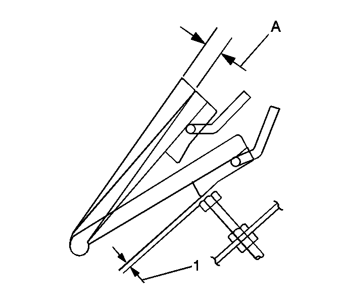
| (a) | Play 5-10mm |
| (1) | Accelerator pedal at full stroke |
TCM-TPS Clearing
- Shift the transmission to 1st gear.
- Turn the ignition ON.
- Turn the overdrive (O/D) OFF (O/D OFF lamp illuminated).
- Press the accelerator pedal to WOT, until you hear the kick-down switch click and hold it (95-100% throttle).
- Press and hold the brake pedal.
- Release the pedals.
- Turn the ignition OFF.
| • | (early TCMs) the CHECK TRANS light will flash 5 times. |
| • | (late TCMs) the CHECK TRANS light will flash 5 times slow and then 6 times fast. |
TCM-DTC Clearing
- Shift the transmission to Neutral.
- Turn the O/D ON.
- Jump pins 1 and 3 of the green TCM Data Link Connector (DLC). Refer to Figure 37.
- Turn the ignition ON. The CHECK TRANS light will flash.
- Press the accelerator pedal to WOT, until you hear the kick-down switch click and hold it (95-100% throttle).
- Press and hold the brake pedal. The CHECK TRANS light will flash 10 times slow and then flash fast.
- Release both pedals.
Figure 37
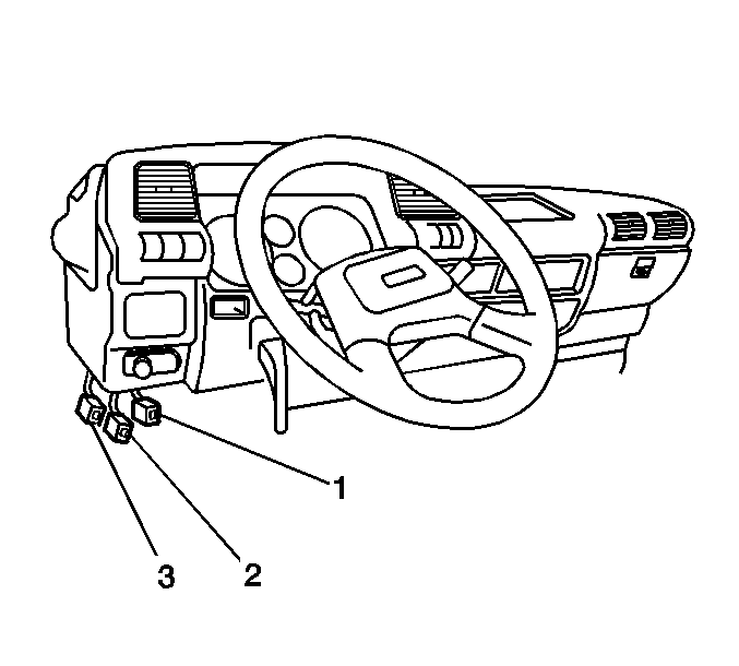
| (1) | DIAG Connector (Green) A/T |
| (2) | DIAG Connector (Creamy White) Emissions |
| (3) | FICD Connector (White) |
Memorize WOT Voltage
- Disconnect the Fast Idle Control Device (FICD) connector. It is a 1-pin white connector located near the green TCM-DLC connector. It is wrapped with blue tape. Refer to Figure 37.
- Shift the transmission to PARK.
- Press the accelerator pedal to WOT until the kick-down switch clicks and hold it (95-100% throttle).
- Press and hold the brake pedal. The CHECK TRANS light should turn on for 3 seconds, flash 3 times slowly and then flash quickly.
- Release the pedals.
Memorize Idle Voltage
- Start the vehicle.
- Press the accelerator pedal to 1000 RPM, 3 times slowly. Allow the pedal to return completely to its rest position each time.
- Turn the ignition OFF.
- Remove the jumper wire from the green TCM-DLC.
- Connect the white 1-pin FICD connector.
Verifying TPS Values Accepted
- Turn the ignition ON. The CHECK TRANS lamp will start flashing.
- Press the accelerator pedal to WOT, until the kick-down switch clicks and hold it (95-100% throttle).
| • | (early TCMs) If the procedure was successful, the CHECK TRANS light will turn off. |
| • | (late TCMs) If the procedure was successful, the CHECK TRANS light will turn off when you release the accelerator pedal. |
| • | If the CHECK TRANS light continues to flash, you will have to start over from Procedure II -- TCM-TPS Clearing. If the procedure continues to fail, check for a problem with the adjustment of the accelerator pedal, kick-down switch or TPS, the accelerator cable/injection pump adjustment, or for TCM-DTCs. |
A/T | Automatic Transmission |
DLC | Data Link Connector |
DTC | Diagnostic Trouble Code |
FICD | Fast Idle Control Device |
O/D | Overdrive |
TCM | Transmission Control Module |
WOT | Wide Open Throttle |
Year | Model | Engine | Trans |
|---|---|---|---|
1999 | W4/W5 | 4HE1 | Aisin A/T 450-43LE |
CHECK TRANS Light Operation
The following procedures are for manually pulling Transmission Control Module (TCM) Diagnostic Trouble Codes (DTCs), how to read TCM-DTCs, and how to manually clear TCM-DTCs.
Manually Reading TCM-DTCs
- Jump between pins 1 and 3 of the green TCM-DLC. Refer to Figure 37.
- Turn the ignition ON. The CHECK TRANS light will flash when there is a failure in one of its monitored circuits. The light will turn off as soon as the condition that caused the failure is corrected. The code will be stored in a history memory.
DTC Notes
- If the lamp flashes ON and OFF, Code 1, there are no DTCs stored.
- Turn the ignition OFF.
- Disconnect the jumper wire.
| • | The 10s digit of a code is flashed first and then the 1s digit. |
| • | Each code is flashed 3 times in a continuous cycle. |
| • | Codes will flash until the jumper wire is removed. |
Manually Clearing TCM-DTCs
- Jump pins 1 and 3 of the green TCM-DLC. Refer to Figure 37.
- Shift the transmission into Neutral.
- Turn the ignition ON.
- Press the accelerator pedal until you hear the kick-down switch click, and hold it (95-100% throttle).
- Press and hold the brake pedal. If the procedure was successful, the CHECK TRANS lamp will flash fast and then slow.
ECM Inspection 1994 W4/W5 4-Cyl MI-TICS
Year | Model | Engine |
|---|---|---|
1999 | W4/W5 | 4HE1 |
Engine ECM Actuator Self Test
This procedure places the Engine Control Module (ECM) in an actuator self-test mode and accesses self-diagnosis. It will cycle the solenoids for the Exhaust Gas Recirculation Valve (EGR), aneroid compensator, Fast Idle Control Device (FICD), and the Variable Swirl System (VSS) and flash Diagnostic Trouble Codes (DTCs) from the glow plug lamp.
- Use a 1500 resistor (or the ENG jumper of the quality check tool) to jump pins 1 and 3 of the DLC (white 3-pin connector in left kick panel). Refer to Figures 37 and 40.
- Start the vehicle.
- Code 12 will continue to flash from the glow plug lamp (or a DTC may be displayed if there is a fault). Refer to Figure 38.
- The vehicle's idle will surge up and down.
- Make sure each of the emission devices operate. Refer to Figure 39.
- Accelerate to 2,000 RPM (3 times) to exit the self test.
- Any fail codes will continue to be flashed through the glow plug lamp.
- Turn the ignition OFF.
- Remove the jumper wire.
Figure 38
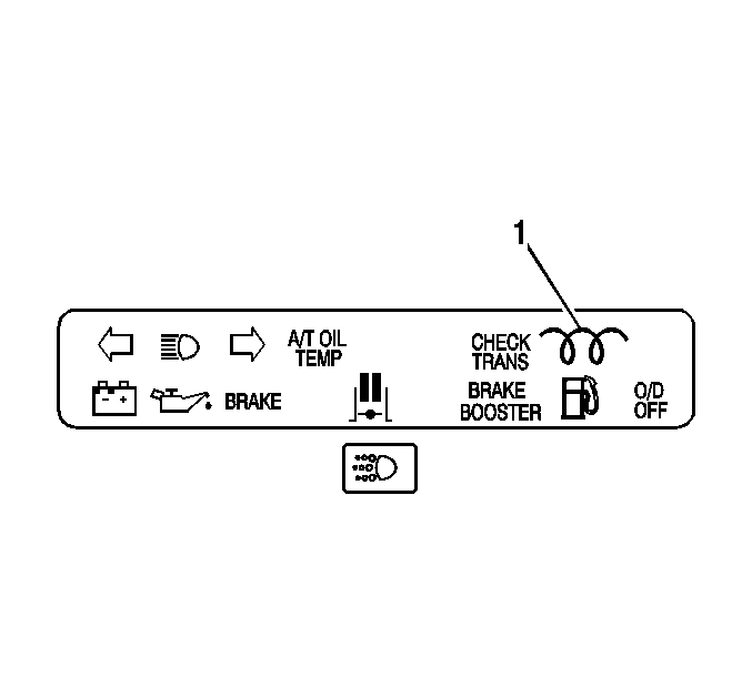
| (1) | Glow Plug Indicator Light |
Figure 39
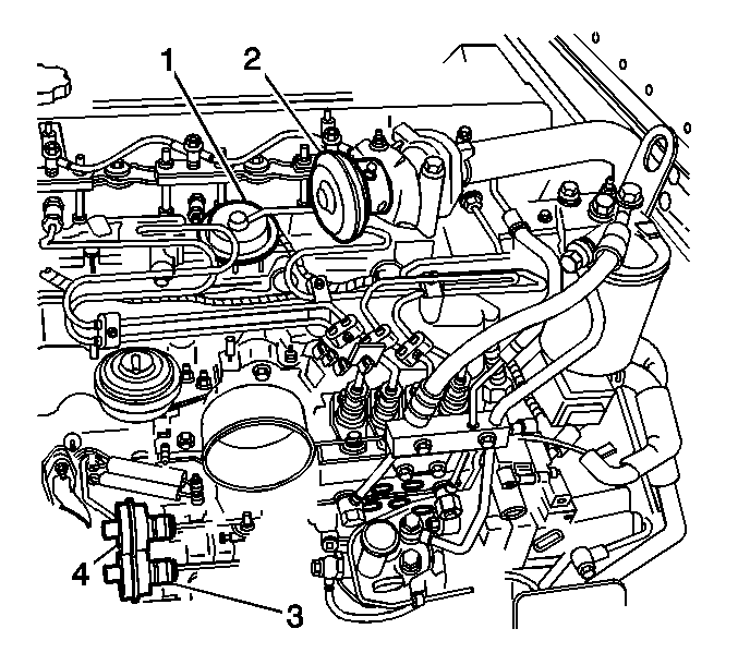
| (1) | VSS Valve |
| (2) | EGR Valve |
| (3) | Aneroid Compensator |
| (4) | FICD |
Figure 40
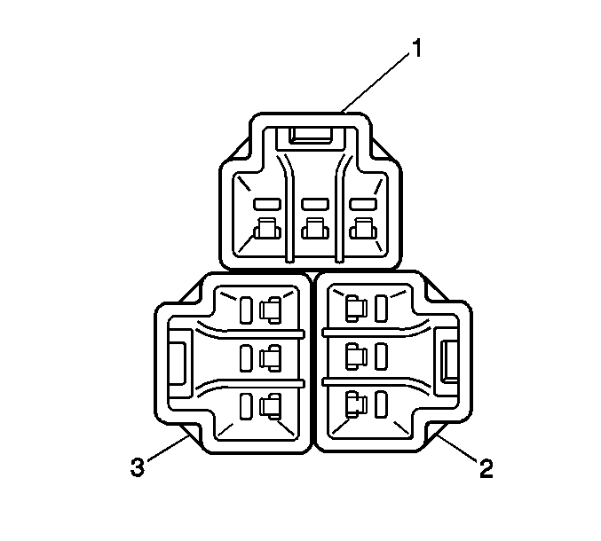
| (1) | A/T (GREEN) |
| (2) | ENG |
| (3) | CLEAR |
Important: The Quality Check Tool is a set of 3 jumper wires. Refer to Figure 40.
• The green connector is a jumper used to diagnose and inspect the
TCM. • The white connector marked ENG is a 1500 OHM resistor used to
place the engine ECM into self-diagnosis and to test the actuators. • The white connector marked CLEAR is a 4700 OHM resistor used to
manually clear engine DTCs.
| • | EGR plunger should move. |
| • | FICD rod should move. |
| • | VSS rod should move. |
| • | Aneroid compensator rod should move. |
Manually Reading ECM Engine DTCs
- Jump pins 1 and 3 of the engine DLC (white 3-pin connector in left kick panel). Refer to Figure 37.
- Turn the ignition ON.
- DTCs will be flashed from the glow plug lamp.
- Each code is flashed 3 times, the 10s digit first and then the ones.
- Code 12 is always flashed to show that communications circuits are good. Stored DTCs always follow Code 12.
- Turn the ignition OFF.
- Remove the jumper wire.
Manually Clearing ECM Engine DTCs
- Use a 4700 resistor (or the clear jumper of the quality check tool) to jump pins 1 and 3 of the engine DLC (white 3-pin connector in left kick panel). Refer to Figures 37 and 40.
- Turn the ignition ON.
- The glow plug lamp will flash 3 times.
- Turn the ignition OFF.
- Disconnect the jumper wire.
- Install the GM Campaign Identification Label.
Campaign Identification label
Each vehicle corrected in accordance with the instructions outlined in this Product Campaign Bulletin will require a "Campaign Identification Label". Each label provides a space to include the campaign number and the five (5) digit dealer code of the dealer performing the campaign service. This information may be inserted with a typewriter or a ball point pen.
Each "Campaign Identification Label" is to be located on the radiator core support in an area which will be visible when the vehicle is brought in by the customer for periodic servicing. When installing the Campaign Identification Label, be sure to pull the tab to allow the adhesion of the clear protective covering. Additional Campaign Identification Labels can be obtained from VISPAC Incorporated by calling 1-800-269-5100 (Monday-Friday, 8:00 am to 4:30 pm Eastern Standard Time). Ask for Item Number S-1015 when ordering.
Apply the "Campaign Identification Label" only on a clean, dry surface.
Claim Information
Submit a Product Campaign Claim with the information indicated below.
Repair Performed | Part Count | Failed Part No. | Parts Allow | CC-FC | Labor Op | Labor Hours* |
|---|---|---|---|---|---|---|
Fuel Injection Pump Drive Gear Replacement (Include Quality Audit Check) | 1-8 | -- | ** | MA-96 | V0254 | 2.8 |
* -- For Campaign Administrative Allowance, add 0.1 hours to the "Labor Hours". ** -- The "Parts Allowance" should be the sum total of the current GMSPO Dealer Net price plus 40% for parts needed to complete the repair. | ||||||
Refer to the General Motors Corporation Claims Processing Manual for details on Product Campaign Claim Submission.
October, 1998Dear Chevrolet/GMC Customer:
This notice is sent to inform you of a recall campaign that includes your vehicle.
Reason For This Recall
General Motors has decided that certain 1999 Chevrolet and GMC W4 and W5 diesel vehicles may exhibit a condition in which the injection pump timing gear may contain a machining burr on the gear surface. This condition may cause the injection pump gear to break, resulting in possible engine damage.
What Will Be Done
To prevent the possibility of this condition occurring, your Chevrolet/GMC dealer will replace the injection pump timing gear. This service will be performed for you at no charge .
Contacting Your Dealer
Please contact your dealer as soon as possible to arrange a service date and to assure parts availability. Instructions for making this correction have been sent to your dealer. Please ask your dealer if you wish to know how much time will be needed to schedule, process, and repair your vehicle.
If you experience any trouble scheduling your vehicle or you have any questions regarding this recall action, please contact the appropriate Customer Assistance/Relations Center at the number listed below:
Division | Number | Deaf, Hearing Impaired, or Speech Impaired* |
|---|---|---|
Chevrolet | 1-800-222-1020 | 1-800-833-2438 |
GMC | 1-800-462-8782 | 1-800-462-8583 |
* Utilizes Telecommunication Devices for the Deaf/Text Telephones (TDD/TTY) | ||
Customer Reply Card
The enclosed customer reply card identifies your vehicle. Presentation of this card to your dealer will assist in making the necessary correction in the shortest possible time. If you no longer own this vehicle, please let us know by completing the postage paid reply card and returning it to us.
We are sorry to cause you this inconvenience; however, we have taken this action in the interest of your continued satisfaction with our products.
Chevrolet/Pontiac-GMC Division
General Motors Corporation
Enclosure
