Tools Required
J 36660-A Electronic Torque Angle Meter
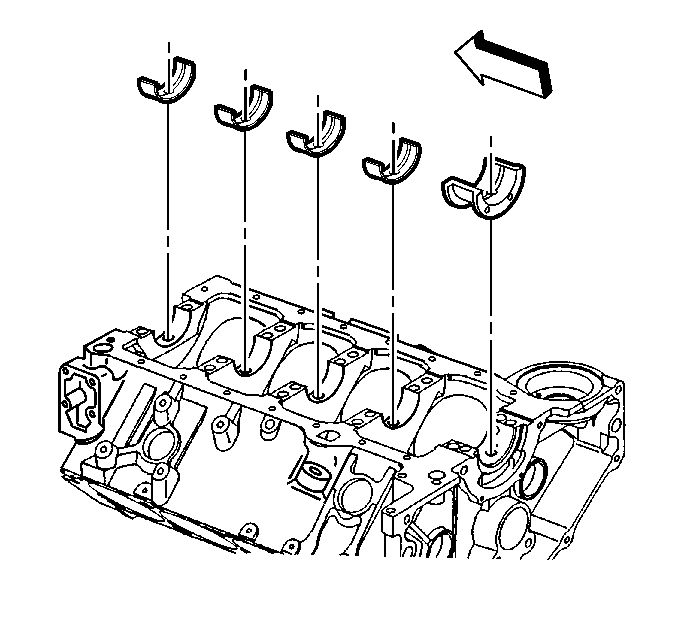
- Install the crankshaft bearings into the engine block.
- Apply clean engine oil to the crankshaft bearings.
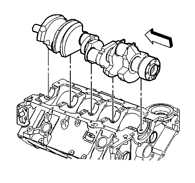
- Apply clean engine oil to the crankshaft bearing journals.
- Install the crankshaft.
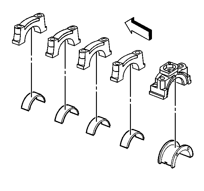
- Install the crankshaft bearings into the crankshaft bearing caps.
- Apply clean engine oil to the crankshaft bearings.
- Install the crankshaft bearing caps in the original positions and with the arrow on the crankshaft bearing caps in the direction of the front of the engine block.
- Install the crankshaft bearing cap bolts and the crankshaft bearing cap studs.
- Thrust the crankshaft rearward in order to set and align the crankshaft thrust bearings and the crankshaft bearing caps.
- Thrust the crankshaft forward in order to align the rear faces of the crankshaft thrust bearings.
- Ensure that the crankshaft bearing caps are fully seated in the engine block crankshaft bearing cap channel, and that the crankshaft bearing caps are centered on the engine block bulkheads.
- Measure the crankshaft end play.
- Tighten the crankshaft bearing cap bolts and the crankshaft bearing cap studs.
- Tighten the crankshaft bearing cap bolts and the crankshaft bearing cap studs on the first pass to 20 N·m (15 lb ft).
- Tighten the crankshaft bearing cap bolts and the crankshaft bearing cap studs (2 bolt caps) on the final pass to 73 degrees using the J 36660-A .
- Tighten the bearing cap outboard bolts (4 bolt caps) on the final pass to 43 degrees using the J 36660-A .
- Tighten the bearing cap inboard bolts and the bearing cap inboard studs (4 bolt caps) on the final pass to 73 degrees using the J 36660-A .
- Rotate the crankshaft in order to check for binding.
- If the crankshaft does not turn freely, loosen the crankshaft bearing cap bolts on 1 crankshaft bearing cap at a time in order to determine the location of the binding.
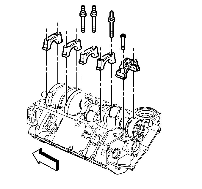
Important: Ensure that the crankshaft bearing cap directional arrow points toward the front of the engine block, and the crankshaft bearing cap is in the original location and position.
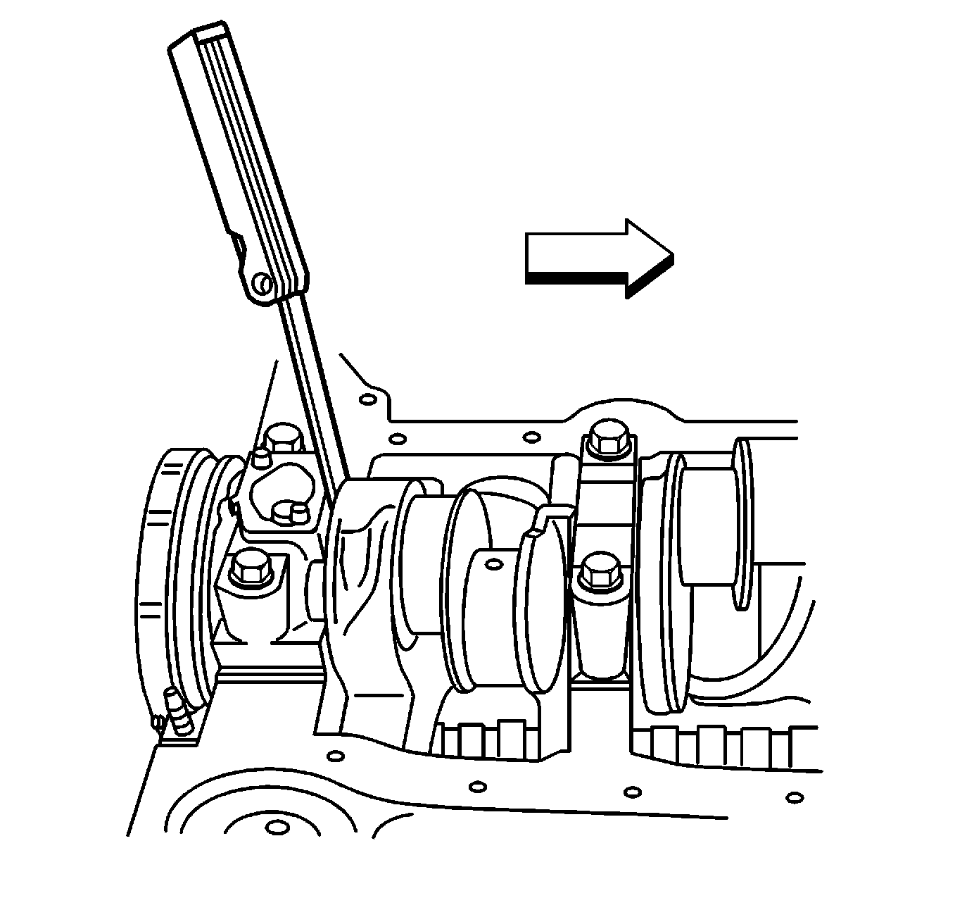
| 12.1. | Tighten the crankshaft bearing cap bolts and the crankshaft bearing cap studs finger tight. |
| 12.2. | Firmly thrust the crankshaft rearward, and then forward. |
This will align the crankshaft rear bearing thrust surfaces.
| 12.3. | With the crankshaft pushed forward, insert a feeler gauge between the crankshaft and the crankshaft rear bearing thrust surface to measure the clearance. |
Specification
Crankshaft end play 0.05-0.20 mm (0.002-0.008 in)
Notice: Use the correct fastener in the correct location. Replacement fasteners must be the correct part number for that application. Fasteners requiring replacement or fasteners requiring the use of thread locking compound or sealant are identified in the service procedure. Do not use paints, lubricants, or corrosion inhibitors on fasteners or fastener joint surfaces unless specified. These coatings affect fastener torque and joint clamping force and may damage the fastener. Use the correct tightening sequence and specifications when installing fasteners in order to avoid damage to parts and systems.
Tighten
A bent crankshaft, or lack of proper crankshaft bearing clearance, may cause binding.
A lack of proper crankshaft bearing clearance may be caused by the following:
| • | Burrs on the crankshaft bearing cap |
| • | Foreign material between the crankshaft bearing and the engine block |
| • | Foreign material between the crankshaft bearing and the crankshaft bearing cap |
| • | Damaged crankshaft bearing |
| • | Improper size crankshaft bearing |
Tools Required
J 36660-A Electronic Torque Angle Meter
- Install the crankshaft bearings into the engine block.
- Apply clean engine oil to the crankshaft bearings.
- Apply clean engine oil to the crankshaft bearing journals.
- Install the crankshaft.
- Install the crankshaft bearings into the crankshaft bearing caps.
- Apply clean engine oil to the crankshaft bearings.
- Install the crankshaft bearing caps in the original positions and with the arrow on the crankshaft bearing caps in the direction of the front of the engine block.
- Install the crankshaft bearing cap bolts and the crankshaft bearing cap studs.
- Thrust the crankshaft rearward in order to set and align the crankshaft thrust bearings and the crankshaft bearing caps.
- Thrust the crankshaft forward in order to align the rear faces of the crankshaft thrust bearings.
- Look to ensure that the crankshaft bearing caps are fully seated in the engine block crankshaft bearing cap channel and that the crankshaft bearing caps are centered on the engine block bulkheads.
- Tighten the crankshaft bearing cap bolts and the crankshaft bearing cap studs.
- Tighten the crankshaft bearing cap bolts and the crankshaft bearing cap studs on the first pass to 20 N·m (15 lb ft).
- Tighten the crankshaft bearing cap bolts and the crankshaft bearing cap studs (two bolt caps) on the final pass to 73 degrees using the J 36660-A .
- Tighten the bearing cap outboard bolts (four bolt caps) on the final pass to 43 degrees using the J 36660-A .
- Tighten the bearing cap inboard bolts and the bearing cap inboard studs (four bolt caps) on the final pass to 73 degrees using the J 36660-A .
- Measure the crankshaft end play.
- Rotate the crankshaft in order to check for binding.
- If the crankshaft does not turn freely, loosen the crankshaft bearing cap bolts on 1 crankshaft bearing cap at a time in order to determine the location of the binding.


Important: Always look to ensure that the crankshaft bearing cap directional arrow point toward the front of the engine block and the crankshaft bearing cap is in the original location and position.
Notice: Use the correct fastener in the correct location. Replacement fasteners must be the correct part number for that application. Fasteners requiring replacement or fasteners requiring the use of thread locking compound or sealant are identified in the service procedure. Do not use paints, lubricants, or corrosion inhibitors on fasteners or fastener joint surfaces unless specified. These coatings affect fastener torque and joint clamping force and may damage the fastener. Use the correct tightening sequence and specifications when installing fasteners in order to avoid damage to parts and systems.
Tighten

| 13.1. | Firmly thrust the crankshaft rearward, and then forward. |
This will align the crankshaft rear bearing thrust surfaces.
| 13.2. | With the crankshaft pushed forward, insert a feeler gauge between the crankshaft and the crankshaft rear bearing thrust surface to measure the clearance. |
Specification
Crankshaft end play 0.05-0.20 mm (0.002-0.008 in)
A bent crankshaft or lack of proper crankshaft bearing clearance may cause binding.
A lack of proper crankshaft bearing clearance may be caused by the following:
| • | Burrs on the crankshaft bearing cap |
| • | Foreign material between the crankshaft bearing and the engine block |
| • | Foreign material between the crankshaft bearing and the crankshaft bearing cap |
| • | Damaged crankshaft bearing |
| • | Improper size crankshaft bearing |
