Tools Required
| • | J 25025-B
Dial Indicator Post and Guide Pin Set |

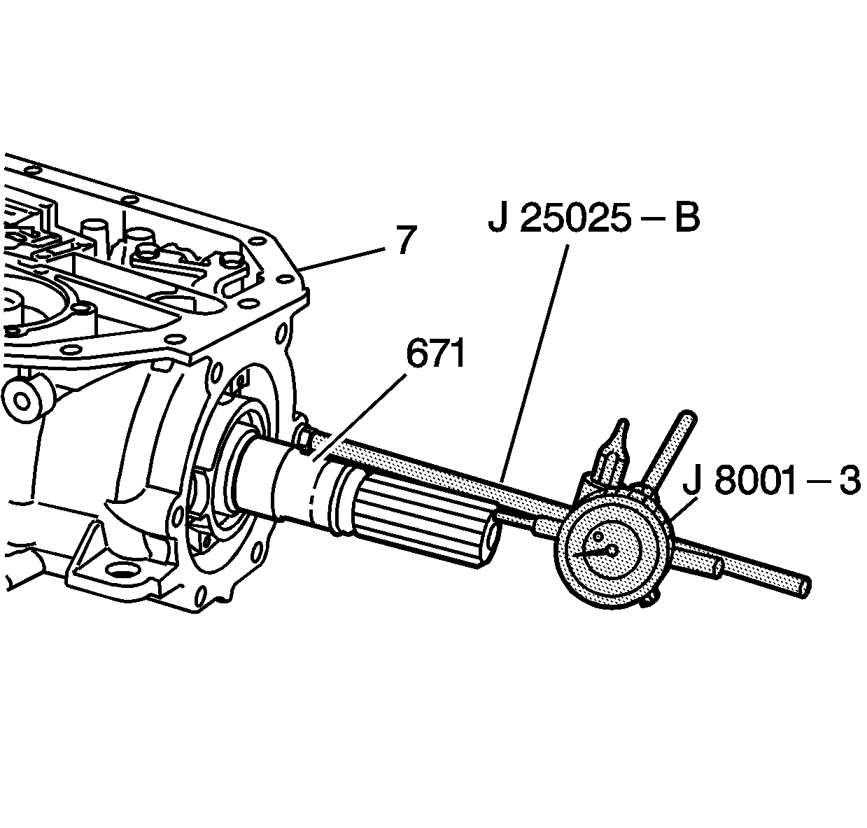
- Assemble the
J 25025-B
by attaching the threaded rod and the dial indicator holder to one of the case
extension bolt holes on the transmission case assembly (7).
- Push in the output shaft assembly (671) to remove any slack.
- Assemble the
J 8001-3
onto the dial indicator holder. Index the
J 8001-3
to the end of the output shaft (671).
- Set the
J 8001-3
to 0.
- Move the output shaft (671) in and out, noting the amount of end play. The correct end play is between 0.127-0.508 mm (0.005-0.020 in).
Important: During reassembly, the rear unit end play check must be repeated in order to verify the accuracy of the selective washer.
- Record this measurement for future reference.
- Remove the tools.
Tools Required
| • | J 25025-B Pump
and Valve Body Alignment Pin Set |

- Assemble the J 25025-B
by attaching the threaded rod and
the dial indicator holder to one of the case extension bolt holes on the transmission
case assembly (7).
- Push in the output shaft assembly (671) to remove any slack.
- Assemble the J 8001-3
onto the dial indicator holder. Index the J 8001-3
to the end of the output shaft (671).
- Set the J 8001-3
to 0.
- Move the output shaft (671) in and out, noting the amount
of end play. The correct end play is between 0.127-0.635 mm (0.005-0.025 in).
Important: During reassembly, the rear unit end play check must be repeated in
order to verify the accuracy of the selective washer.
- Record this measurement for future reference.
- Remove the tools.


