For 1990-2009 cars only
Info - Throttle Position Sensor Replacement Procedure

| Subject: | Throttle Position Sensor Replacement Procedure |
| Models: | 1999-2004 Chevrolet W-Series Medium Duty Tilt Cab Models |
| 1999-2004 GMC W-Series Medium Duty Tilt Cab Models |
| 1999-2004 Isuzu NPR/NQR Commercial Medium Duty Models |
| with 4HE1 Diesel Engine and Aisin Automatic Transmission |
When the throttle position (TP) sensor requires replacement, use the following procedure to correctly replace and adjust the TP sensor.
- Disconnect the negative battery cable.
- Disconnect the kick-down switch connector.
- Disconnect the accelerator cable.
- Disconnect the hand control idle-up cable.
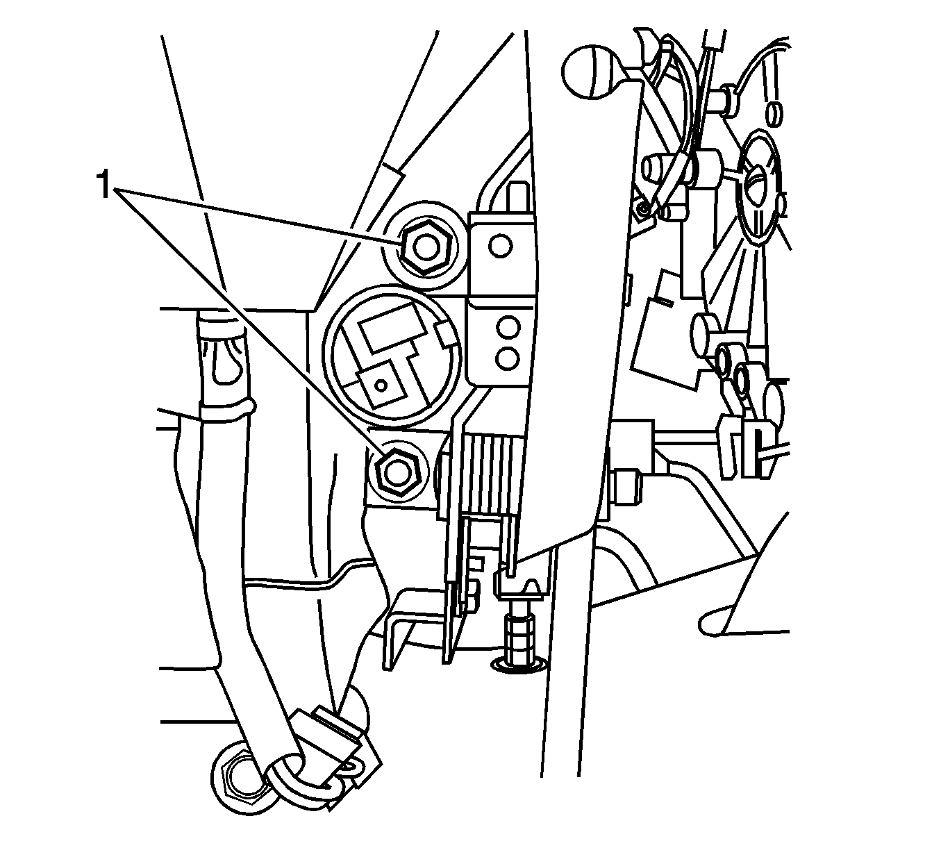
- Remove the two accelerator pedal mounting nuts (1).
- Move the accelerator pedal forward and disconnect the idle switch.
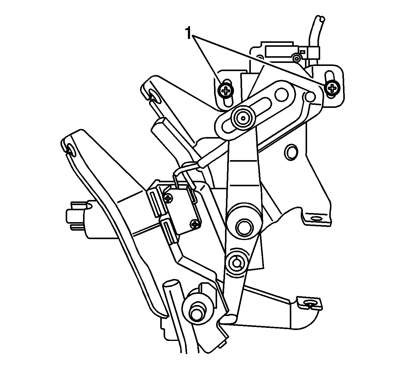
- Pull the accelerator pedal assembly forward in order to access the TP sensor mounting screws (1).
- Remove the two mounting screws and separate the TP sensor from the accelerator pedal.
- Remove the accelerator pedal assembly.
- Push the TP sensor up and over the main dash harness. Pull down then out toward the driver seat.
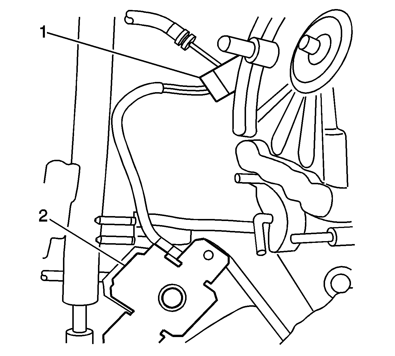
- Position the TP sensor harness connector (1) so that the connector lock can be seen. Using a long screwdriver, press the sensor connector against the cab wall holding the connector in place while also releasing the connector lock. The TP sensor (2) can now be disconnected.
- Push the TP sensor back up and over the main dash harness in order to properly route the harness and connector. This routing is important so that the harness does not interfere or become damaged by the accelerator pedal assembly.
- Connect the negative battery cable.
- Attach the TP sensor to the accelerator pedal assembly. With the pedal resting in the idle position, and using the Tech 2, verify that the sensor reading at idle is within specification (TP sensor idle specification of 4.0-4.5 volts).
- Install the accelerator pedal assembly.
- Connect the hand control idle-up cable.
- Connect the accelerator cable.
- Connect the kick-down switch connector.
- Adjust the following components in order:
- Perform the TP sensor relearn procedure. Refer to Corporate Bulletin Number 02-07-30-025B.


This action should provide enough slack in the TP sensor to expose the connector located at the main dash harness at the back of the heater box.

Important: The new TP sensor can be easily connected to the main harness with one hand. Ensure that the connector lock clicks when installing the new TP sensor.
| 19.1. | The hand control idle-up cable (must be in the OFF position) |
| 19.2. | The accelerator cable (remove all slack) |
| 19.3. | The accelerator pedal stop bolt (should be 0-2 mm (0-0.079 in) |
| 19.4. | The kick-down switch (should be 95-100 percent) |
Warranty Information
For vehicles repaired under warranty, use:
Labor Operation | Description | Labor Time |
|---|---|---|
J6374 | Sensor, Throttle Position - Replace | 1.2 hrs* |
*This labor time includes the TP Sensor Relearn Procedure. | ||
