Water Pump Replacement General
Removal Procedure
- Disconnect the negative battery cable. Refer to
Caution: Unless directed otherwise, the ignition and start switch must be in the OFF or LOCK position, and all electrical loads must be OFF before servicing any electrical component. Disconnect the negative battery cable to prevent an electrical spark should a tool or equipment come in contact with an exposed electrical terminal. Failure to follow these precautions may result in personal injury and/or damage to the vehicle or its components.
in General Information. - Drain the coolant from the radiator. Refer to Draining, Filling, Recovery of Cooling System.
- Remove the drive belt. Refer to Accessory Drive Belt in Engine Mechanical.
- Remove the fan clutch. Refer to Fan Clutch Replacement.
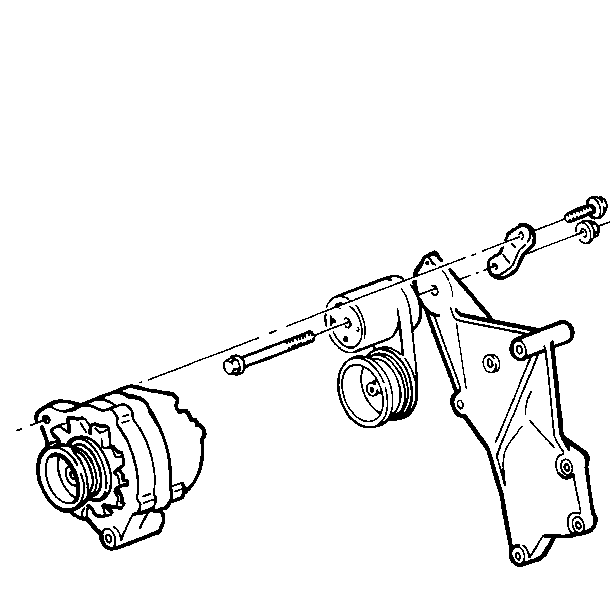
- Remove the generator and the upper and lower mounting brackets.
- Remove the power steering pump from the mounting brackets and lay it aside. Do not disconnect the power steering hoses. Refer to Power Steering Pump in Power Steering Pump and Gear.
- Remove the power steering pump mounting brackets. Refer to Power Steering Pump in Power Steering Pump and Gear.
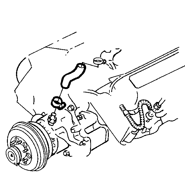
- Disconnect the lower radiator hose from the coolant pump.
- Disconnect the bypass hose from the pump.
- Remove the oil filler tube from the coolant pump plate.
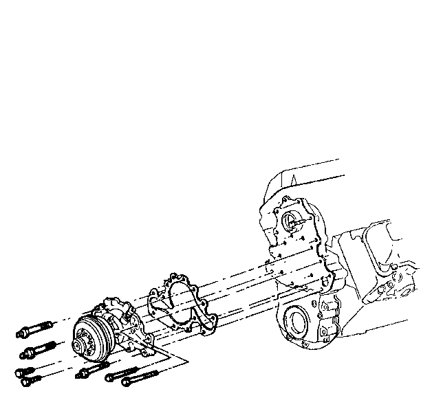
- Remove the two short bolts, the two long bolts and the three studs from the pump.
- Remove the two short studs, the four bolts, and the coolant pump plate from the engine block.
- Remove the hidden bolt from the rear of the coolant pump plate.
- Remove the coolant pump and the gasket from the coolant pump plate.
- Clean all flanges so that they are free of oil.
- Clean the mating surfaces of the coolant pump, both sides of the coolant pump plate, and the engine block.
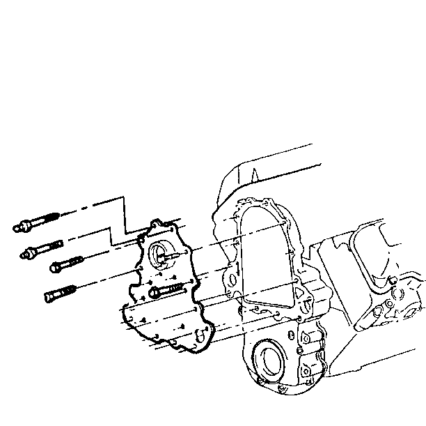
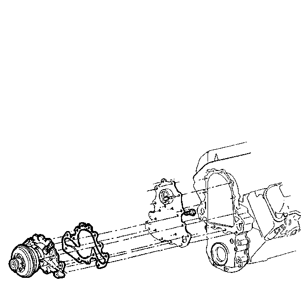
Installation Procedure
- Install the gasket on the coolant pump.
- Install the coolant pump on the coolant pump plate with the hidden bolt from the rear of the plate.
- Install the coolant pump and the plate to the engine with the two short studs, the four bolts, the three long studs, the two long bolts and the two short bolts.
- Install the oil filler tube to the coolant pump plate.
- Connect the bypass hose to the coolant pump with a clamp.
- Connect the lower radiator hose to the coolant pump with a clamp.
- Install the power steering pump mounting brackets. Refer to Power Steering Pump in Power Steering Pump and Gear.
- Install the power steering pump on the mounting brackets. Refer to Power Steering Pump in Power Steering Pump and Gear.
- Install the upper and lower generator mounting brackets and the generator.
- Install the fan clutch. Refer to Fan Clutch Replacement.
- Install the drive belt. Refer to Accessory Drive Belt in Engine Mechanical.
- Fill the radiator with coolant. Refer to Draining, Filling, Recovery of Cooling System.
- Connect the negative battery cable.

Tighten
Tighten the bolt to 23 N·m (17 lb ft).
Notice: Use the correct fastener in the correct location. Replacement fasteners must be the correct part number for that application. Fasteners requiring replacement or fasteners requiring the use of thread locking compound or sealant are identified in the service procedure. Do not use paints, lubricants, or corrosion inhibitors on fasteners or fastener joint surfaces unless specified. These coatings affect fastener torque and joint clamping force and may damage the fastener. Use the correct tightening sequence and specifications when installing fasteners in order to avoid damage to parts and systems.
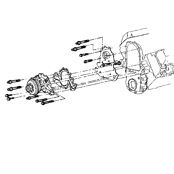
| • | Apply anaerobic sealer (GM P/N 1052357 or the equivalent). |
| • | The sealer must be wet to the touch when the bolts are tightened. |
Tighten
The four bolts, the two short studs, and the two short bolts to 23 N·m
(17 lb ft).
Tighten
Tighten the three long studs and the two long bolts to 42 N·m
(31 lb ft).


For information concerning replacement of the components on the Caterpillar® engine in the P92 chassis, refer to the Caterpillar® Operation & Maintenance Manual.
Water Pump Replacement Belt
Removal Procedure
- Remove the serpentine belt. Refer to Accessory Drive Belt earlier in Engine Mechanical.
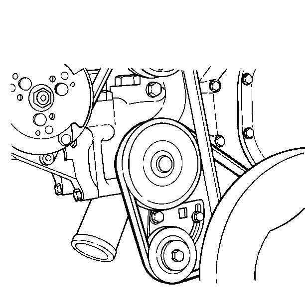
- Loosen the two bolts holding the coolant pump tensioner in place.
- Slip the coolant pump belt off the coolant pump and the crankshaft pulleys.
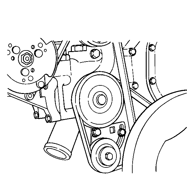
Installation Procedure
- Place the coolant pump belt around the crankshaft, the coolant pump, and the coolant pump tensioner by hand.
- Insert a 1/2 inch drive breaker bar into the belt tensioner. Pry until the belt is tight, but do not overtighten the coolant pump belt.
- Tighten the tensioner holding bolts until they hold the tensioner in place.
- Check the coolant pump belt tension. Refer to Coolant Pump Replacement (Belt Adjustment).
- If the belt tension is correct, tighten the pivot and holding bolts until the tensioner is held in place securely.
- Install the accessory drive belt. Refer to Accessory Drive Belt in Engine Mechanical.
NOTICE: Do not force the belt onto a pulley by prying with a screwdriver, a crowbar, or any other wedge-type tool. prying a belt into position can damage both the belt and the pulley. If the tensioner is completely out of the way and the belt will not fit, it is too small and a larger belt is needed.


Water Pump Replacement Belt Adjustment
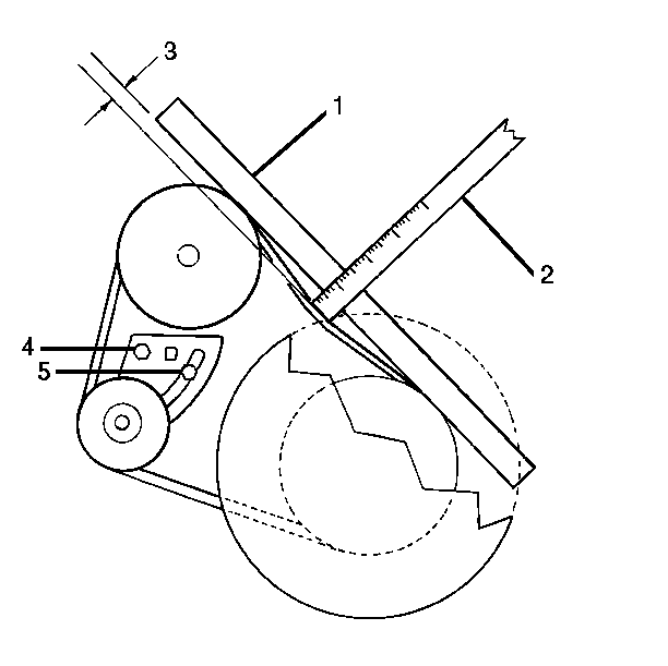
- Lay a straight edge (1) against the coolant pump pulley and the crankshaft pulley.
- Put a ruler (2) with the "0" end of the scale against the belt. Push it at a right angle to the straight edge (1).
- Read the amount of deflection (3) on the scale.
- If the belt is tightened to the correct tension, the deflection will read between 9 - 15 mm (3/8 - 5/8 in).
- If the belt tension is not correct, loosen the pivot bolt (4) and the bracket bolt (5) and insert a breaker bar into the tensioner. Pry or loosen until it seems correct, then recheck the tension.
- Tighten the pivot bolt (4) and the bracket bolt (5) when finished.
