Removal Procedure
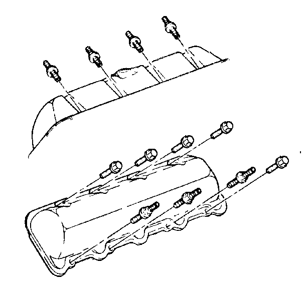
- Remove the rocker arm cover. Refer to Valve Rocker Arm Cover Replacement.
- Remove the rocker arm shaft with the rocker arms and the pushrods. Refer to Rocker Arm and Pushrod Replacement.
- Remove the cylinder head. Refer to Cylinder Head Replacement.
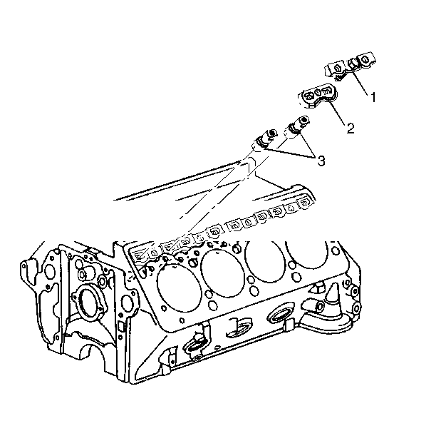
- Remove the clamps
- Remove the guide plates. Use mechanical fingers if necessary.
- Remove the hydrualic lifters using a stick magnet.

Important: Rocker arm assemvlies and pushrods must be marked for proper assembly.


Place the lifters in an organizer rack. The lifters must be installed in the same bore from which they were removed.
Inspection Procedure
- Inspect the hydraulic lifter body for scuffing and scoring. If present, replace the filter.
- Inspect the roller for looseness and excessive play.
- Examine the roller surface for pits and roughness

Check for missing or broken needle bearings. Replace the bearings if necessary.
If present, the mating camshaft lobe should also be checked. If the lobe is pitted or rough, replace the camshaft and the lifter.
Installation Procedure
- Install the hydraulic lifters to the engine.
- Install the guide plates.
- Attach the clamps
- Turn the crankshaft by hand 720 degrees (two full turns) to ensure free movement of the lifters in the guide plates.
- Install the cylinder head. Refer to Cylinder Head Replacement.
- Install the rocker arm shaft with the rocker arms and the pushrods in their original locations. The hardened rends of the pushrods must face up. Refer to Rocker Pushrod Replacement.
- Install the rocker arm cover. Refer to Rocker Arm Cover Replacement.
Notice: New hydraulic lifters must be primed before installation. If the lifters are dry when the engine is started, damage to the lifters may result.
Important: Prime the new hydrualic lifters before installation. Work the lifter plunger while it is submerged in clean kerosene or diesel fuel. Coat the lifter roller and the bearings with lubricant (GM P/N 1052365 or the equivalent). The lifters must be installed in their original locations.

Tighten
Tighten the clamp bolt to 26 N·m (18 lb ft).
Notice: Use the correct fastener in the correct location. Replacement fasteners must be the correct part number for that application. Fasteners requiring replacement or fasteners requiring the use of thread locking compound or sealant are identified in the service procedure. Do not use paints, lubricants, or corrosion inhibitors on fasteners or fastener joint surfaces unless specified. These coatings affect fastener torque and joint clamping force and may damage the fastener. Use the correct tightening sequence and specifications when installing fasteners in order to avoid damage to parts and systems.
If the engine will not turn over by hand, one or more of the lifters may be binding in the guide plate.


