Instrument Cluster P72
Important: The instrument cluster is a static sensitive unit. Great care must be taken when handling it.

When replacing a speedometer or odometer assembly, federal law requires that the odometer reading of the replacement unit be set to register the same mileage as the prior odometer. If the same mileage cannot be set, the law requires that the replacement odometer be set at zero and a label be installed on the driver's door frame to show the previous odometer reading and the date of replacement.
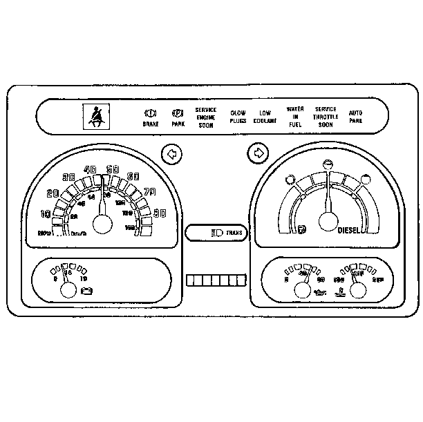
The P72 chassis instrument cluster comes as a single, self-contained unit which includes all gauges, meters and warning lamps. The coach manufacturer is responsible for installing the cluster.
Instrument panel gauges indicate.
| • | The vehicle speed |
| • | The fuel tank level |
| • | The battery voltage |
| • | The coolant temperature |
| • | The oil pressure |
The warning lamps inform the operator if the following occur.
| • | There are problems with the service or parking brakes. |
| • | The engine, the transmission, or the throttle requires service. |
| • | The coolant level is too low. |
| • | There is water in the fuel. |
| • | The engine is ready to start. |
| • | The seat belts have not been connected. |
| • | The high-beam headlamps are on. |
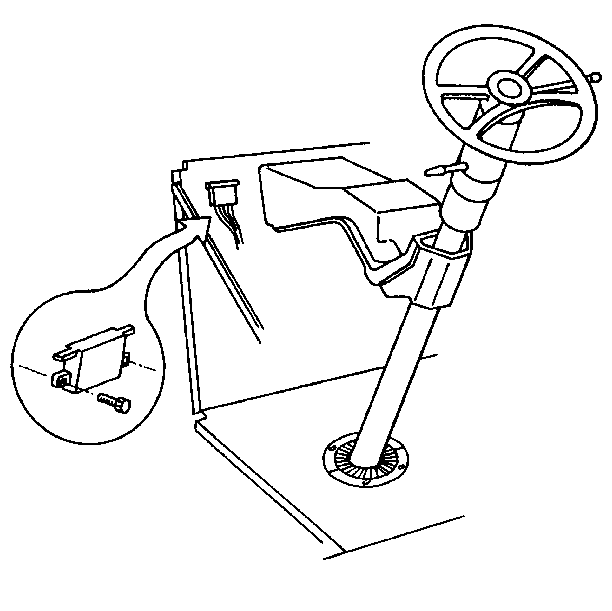
Illumination bulbs located on the rear of the instrument cluster are the only replaceable components on this unit.
Speedometer Assembly

An electric speedometer drive is standard equipment on both models. Lighting is provided by removable bulb and socket assemblies that are inserted into the back of the instrument cluster.
The instrument cluster speedometer system consists of the following.
| • | The vehicle speed sensor (VSS) buffer module (P72 chassis) |
| • | The vehicle speed sensor (VSS) |
| • | The related wiring |
On the P72 chassis, a one-piece instrument cluster mounts in front of the driver in the instrument panel and is not serviceable. Replace the instrument cluster if diagnosis leads to a malfunction. Repairs to the instrument cluster can only be performed by an authorized instrument cluster service center.
The VSS buffer module is a solid-state device that changes the analog output from the vehicle speed sensor to a digital signal containing 4,000 pulses per mile (PPM) for the instrument cluster. The VSS buffer module is matched to the final drive and the tire size of each vehicle. The VSS buffer module must be replaced with the proper replacement VSS buffer module to match that vehicle. If the final drive or tire size is changed for any reason, the VSS buffer module must be changed to match the new final drive or tire size. If not, the signal will not be accurate for proper speedometer/odometer operation. An incorrect VSS buffer module will affect the electronic control module (ECM) and any system that relies on a vehicle speed input.
On the P92 chassis, the speedometer is mounted on the instrument panel assembly. The speedometer can be removed for repair. Repair of the speedometer must be performed by an authorized speedometer repair facility.
The VSS is a permanent magnet signal generator. The VSS sends an analog signal proportional to the propeller shaft speed to the VSS buffer module (P72) and the PCM. The VSS mounts to the transmission tailshaft extension housing.
Fuel Gauge
The fuel gauge indicates the quantity of fuel in the tank when the ignition switch is in RUN. When the ignition switch is turned to any other position, the pointer may come to rest anywhere. The pointer is moved by changes in the magnetic fields of two coils mounted at right angles to each other and connected to the voltage source, the ground and the transducer (the fuel gauge sender). One coil is designate as the EMPTY coil and the other is the FULL coil.
Voltage to the circuit is supplied through a fuse or circuit breaker. When the fuel tank is full, the resistance in the transducer is high. Current flows through the FULL coil and the transducer to ground. The needle will indicate a full tank.
As the fuel level drops, the resistance of the transducer is reduced. More current will flow through the EMPTY coil to ground through the transducer than will flow through the FULL coil. The needle will indicate the lower fuel level on the face of the gauge. When the fuel gauge reads empty, there is probably still some fuel in the tank. This is due to the nature of the fuel gauge and not to be considered a reserve.
Corroded connections or severed ground paths generally cause the indicator to register above full on the gauge face. Short circuits to ground generally result in the indicator resting below empty.
The fuel gauge sender assembly mounts to the top of the fuel tank and is retained by a cam-type locking ring. A seal is used between the fuel tank and the sender. The fuel gauge sender assembly consists of a float attached to a variable resistance sender, a woven plastic filter on the fuel pickup tube, and a vane-type electric fuel pump.
The fuel gauge sender will have two or three hose connections. One is used for the fuel feed hose. The second connects to the vapor canister. The third is used for the fuel return line to the fuel tank. On some fuel tank senders, a short connector lead is used while others have the connector attached directly to the sender.
Oil Pressure Gauge
The oil pressure gauge indicates engine oil pressure with the ignition in RUN. An oil pressure sensor in the engine block changes resistance with oil pressure.
The oil pressure sensor is located at the rear of the engine block on the 6.5L engine for the P72. The oil pressure sensor is located on the left side of the block near the right frame side rail for the P92.
Coolant Temperature Gauge
The coolant temperature gauge measures the current from a variable resistance sensor in the engine coolant passage with the ignition switch in RUN. The sensor changes resistance with coolant temperature. As the coolant temperature increases, the resistance decreases.
The coolant temperature for the P72 sensor is located at the right rear of the vehicle, near the glow plugs. On the P92, the coolant temperature sensor is located below the thermostat.
Voltmeter
With the ignition in RUN or START, voltage is supplied from the 40 A circuit breaker to the tone generator. The tone generator receives signals from the following activated components.
| • | The air and oil pressure switch |
| • | The coolant temperature switch |
| • | The brake overstroke indicator switches |
| • | The low coolant probe |
Instrument Cluster P92

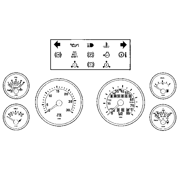
The P92 chassis instruments come on a panel assembly. The panel is supplied to the coach manufacturer, which is responsible for installation. The gauges on the panel are manufactured by VDO.
The gauges on the instrument panel keep the operator informed of the following conditions.
| • | The vehicle speed |
| • | The engine speed |
| • | The fuel tank level |
| • | The battery voltage |
| • | The coolant temperature |
| • | The oil pressure |
The warning lamps inform the operator if the following occur.
| • | There are problems with the service brakes. |
| • | The anti-lock brake system (ABS) requires attention. |
| • | The parking brake is applied. |
| • | There is a problem with the transmission shift control. |
| • | The transmission fluid is too hot. |
| • | The coolant level is too low or the temperature is too high. |
| • | The air tank pressure is too low. |
| • | The high-beam headlamps are on. |

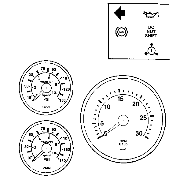
If the P92 chassis is equipped with air suspension, the engine oil pressure gauge will be replaced by a front air pressure gauge. The voltmeter will be replaced by a rear air pressure gauge.
Important: Not all coach manufacturers use the supplied gauges, warning lamps and indicator lamps. Contact the coach manufacturers for service information.
Speedometer Assembly

An electric speedometer drive is standard equipment on both models. Lighting is provided by removable bulb and socket assemblies that are inserted into the back of the instrument cluster.
The instrument cluster speedometer system consists of the following.
| • | The vehicle speed sensor (VSS) buffer module (P72 chassis) |
| • | The vehicle speed sensor (VSS) |
| • | The related wiring |
On the P72 chassis, a one-piece instrument cluster mounts in front of the driver in the instrument panel and is not serviceable. Replace the instrument cluster if diagnosis leads to a malfunction. Repairs to the instrument cluster can only be performed by an authorized instrument cluster service center.
The VSS buffer module is a solid-state device that changes the analog output from the vehicle speed sensor to a digital signal containing 4,000 pulses per mile (PPM) for the instrument cluster. The VSS buffer module is matched to the final drive and the tire size of each vehicle. The VSS buffer module must be replaced with the proper replacement VSS buffer module to match that vehicle. If the final drive or tire size is changed for any reason, the VSS buffer module must be changed to match the new final drive or tire size. If not, the signal will not be accurate for proper speedometer/odometer operation. An incorrect VSS buffer module will affect the electronic control module (ECM) and any system that relies on a vehicle speed input.
On the P92 chassis, the speedometer is mounted on the instrument panel assembly. The speedometer can be removed for repair. Repair of the speedometer must be performed by an authorized speedometer repair facility.
The VSS is a permanent magnet signal generator. The VSS sends an analog signal proportional to the propeller shaft speed to the VSS buffer module (P72) and the PCM. The VSS mounts to the transmission tailshaft extension housing.
Fuel Gauge
The fuel gauge indicates the quantity of fuel in the tank when the ignition switch is in RUN. When the ignition switch is turned to any other position, the pointer may come to rest anywhere. The pointer is moved by changes in the magnetic fields of two coils mounted at right angles to each other and connected to the voltage source, the ground and the transducer (the fuel gauge sender). One coil is designate as the EMPTY coil and the other is the FULL coil.
Voltage to the circuit is supplied through a fuse or circuit breaker. When the fuel tank is full, the resistance in the transducer is high. Current flows through the FULL coil and the transducer to ground. The needle will indicate a full tank.
As the fuel level drops, the resistance of the transducer is reduced. More current will flow through the EMPTY coil to ground through the transducer than will flow through the FULL coil. The needle will indicate the lower fuel level on the face of the gauge. When the fuel gauge reads empty, there is probably still some fuel in the tank. This is due to the nature of the fuel gauge and not to be considered a reserve.
Corroded connections or severed ground paths generally cause the indicator to register above full on the gauge face. Short circuits to ground generally result in the indicator resting below empty.
The fuel gauge sender assembly mounts to the top of the fuel tank and is retained by a cam-type locking ring. A seal is used between the fuel tank and the sender. The fuel gauge sender assembly consists of a float attached to a variable resistance sender, a woven plastic filter on the fuel pickup tube, and a vane-type electric fuel pump.
The fuel gauge sender will have two or three hose connections. One is used for the fuel feed hose. The second connects to the vapor canister. The third is used for the fuel return line to the fuel tank. On some fuel tank senders, a short connector lead is used while others have the connector attached directly to the sender.
Oil Pressure Gauge
The oil pressure gauge indicates engine oil pressure with the ignition in RUN. An oil pressure sensor in the engine block changes resistance with oil pressure.
The oil pressure sensor is located at the rear of the engine block on the 6.5L engine for the P72. The oil pressure sensor is located on the left side of the block near the right frame side rail for the P92.
Coolant Temperature Gauge
The coolant temperature gauge measures the current from a variable resistance sensor in the engine coolant passage with the ignition switch in RUN. The sensor changes resistance with coolant temperature. As the coolant temperature increases, the resistance decreases.
The coolant temperature for the P72 sensor is located at the right rear of the vehicle, near the glow plugs. On the P92, the coolant temperature sensor is located below the thermostat.
Voltmeter
With the ignition in RUN or START, voltage is supplied from the 40 A circuit breaker to the tone generator. The tone generator receives signals from the following activated components.
| • | The air and oil pressure switch |
| • | The coolant temperature switch |
| • | The brake overstroke indicator switches |
| • | The low coolant probe |
Instrument Cluster Circuit Operation
The operation of an individual indicator is described along with its circuit.
Park Brake Warning Light
Battery voltage is supplied to the park brake warning light when the ignition switch is in RUN or START. The park brake switch provides a ground when the park brake is applied. The park brake warning light goes on in order to alert the driver.
Brake Warning Light
Battery voltage is supplied to the brake warning light when the ignition switch is in RUN or START. The brake pressure switch closes in order to provide a ground. The brake pressure switch illuminates the light when there is a loss of brake fluid pressure in one of the two brake systems. This could be caused by a leak in one of the two brake lines.
Fuel Gauge
The fuel gauge pointer is moved by the magnetic fields of two coils. The coils are at right angles to each other. Battery voltage is supplied to the E-coil and the circuit divides at the opposite end of the coil. One path continues to ground through the F-coil. Another goes to ground through the variable resistor of the fuel gauge sender.
When the fuel tank is low, the resistance of the sender is low. A large flow of current passes through the E-coil and the fuel gauge sender resistor. This moves the pointer towards E on the scale. When the fuel tank is full, the sender resistance is high. More current now flows through the F-coil, moving the pointer towards F on the scale.
Oil Pressure Gauge
The engine oil pressure is displayed by the oil pressure gauge. The pointer of the gauge is moved by two coils. The pointer operation is similar to that of the fuel gauge.
The oil pressure sender is connected to the junction of the two coils. The sender has low resistance when the oil pressure is high. This changing resistance changes the current flow through the coils. The magnetic fields of the coils move the pointer from LOW to HIGH.
Engine Coolant Temperature Gauge
The engine coolant temperature gauge is operated by two coils. Battery voltage is supplied to both coils. One coil is grounded through the engine coolant temperature sender. This coil has 55 ohms of resistance at 127 ° C (260 ° F) (hot coolant). The coil's resistance becomes greater at lower temperatures. At 38 ° C (100 ° F), the resistance would be approximately 1400 ohms. This causes the current through the sender and one coil to increase, moving the pointer, as the coolant temperature increases.
Engine Coolant Level Indicator
The engine coolant level indicator comes on in order to warn the driver when the radiator coolant levels are low. Battery voltage is supplied to the engine coolant level indicator. When the engine coolant level is low, the engine coolant level indicator probe will provide a ground to the engine coolant level indicator.
