Starter Inspection 28-MT
Cleaning Procedure
Notice: Do not use grease dissolving solvents for cleaning the overrunning clutch
or armature. Solvents dissolve the grease packed in the clutch and damage
the armature and the field coil insulation.
Clean all starter motor parts with a soft cloth prior to
testing.
Inspection Procedure
Inspection in the following steps refers to visual inspection of the
starter motor parts and assemblies in order to determine the serviceability
of the parts.
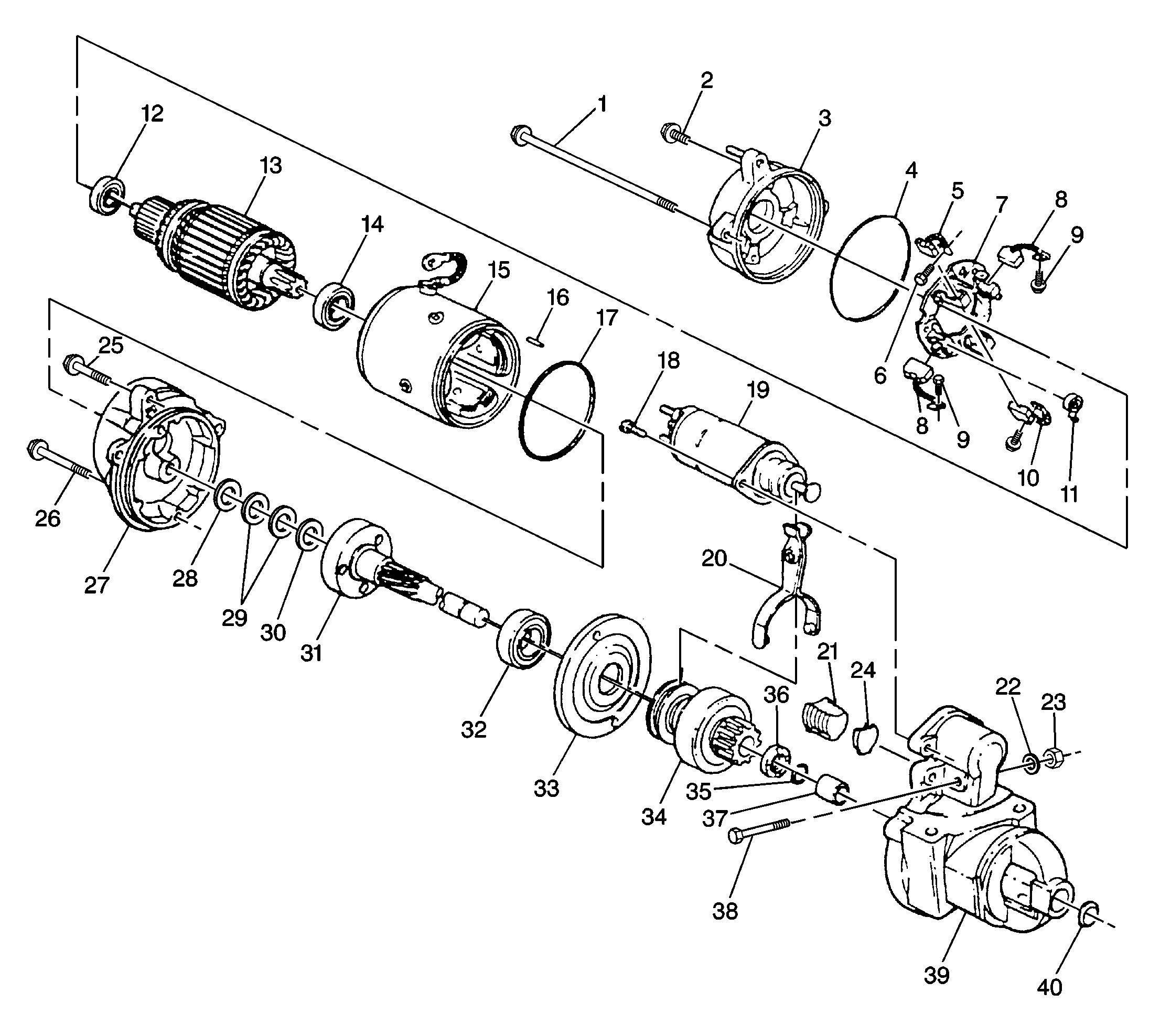
For 28-MT starter motor and components, refer to
- Inspect all parts for cracks, distortion, or other structural
damage. Replace parts and assemblies that are cracked, bent, or otherwise
damaged.
- Inspect the threaded parts for stripped, crossed, or otherwise
damaged threads. Replace parts as necessary.
| • | Replace the parts with thread damage that cannot be cleaned up
using a suitable tap or die. |
| • | Replace any hardware items that have damaged threads. |
- Inspect the solenoid assembly for a cut or torn boot. If the boot
is damaged, replace the solenoid assembly.
- Inspect the clutch drive assembly. Replace the clutch drive assembly
as necessary. Look for the following damage:
| • | The pinion gear turns roughly or turns in both directions. |
| • | The pinion gear teeth are broken or show evidence of step wear. |
| • | The shift lever collar shows deep scoring or other damage. |
- Inspect the brush holder assembly. Replace the brush holder assembly,
if the assembly is damaged. Look for the following damage:
| • | Cracked or broken insulation |
- Inspect the brushes. The minimum allowable brush length is 12 mm
(0.472 in). Replace excessively worn brushes in sets.
- Inspect the drive end housing bushing for scoring or other damage.
Replace a damaged bushing. Refer to

- Inspect the ball bearings using the following procedure:
| 8.1. | Hold the armature or driveshaft and slowly rotate the outer bearing
race by hand. |
| 8.2. | Make sure that the bearing turns freely without binding or the
feel of flat spots. |
| 8.3. | Replace damaged bearings. Refer to Armature Bearing Replacement
below. |
- Inspect the armature assembly for the following conditions:
| • | Gear teeth that are broken, or that show evidence of step wear
or root interference |
| • | Rough commutator surface |
| | Important: Do not turn the commutator in a lathe.
|
| • | Polish a rough surface with 400 grit polishing cloth. |
| • | Thoroughly clean metal dust from between the commutator bars. |
| • | If the commutator surface cannot be repaired in this manner, replace
the armature assembly. |
| | Important: Do not undercut the insulation.
|
| • | Worn commutator with an outer diameter of less than 36 mm (1.378 in),
or if the undercut depth is less than 0.2 mm (0.008 in). |
- Inspect the driveshaft. Replace the driveshaft, if the driveshaft
is damaged. Look for the following conditions:
| • | Scored or damaged driveshaft where the driveshaft turns in the
bushing |
| • | Internal gear with teeth broken or showing evidence of step wear |
| • | Damage spline where the clutch drive assembly does not slide smoothly
and easily over the full length of the spline |
Component Electrical Testing
Do the following electrical tests in order to determine the serviceability
of the starter assemblies.
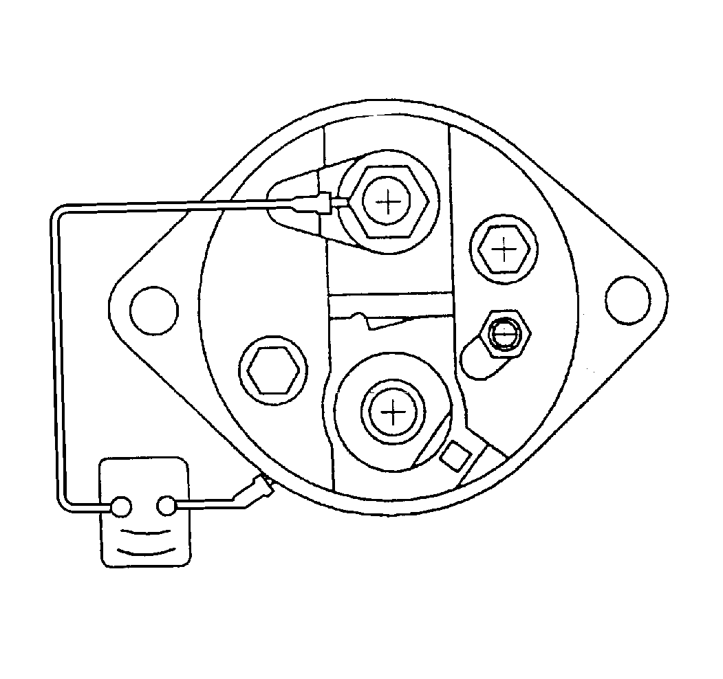
- Using an ohmmeter, check
the windings of the solenoid assembly for continuity using the following
procedure:
| • | Check the resistance of the solenoid pull-in and hold-in windings
in a series by measuring the resistance between the motor terminal and the
solenoid case. |
| • | A resistance reading well above 1.95 ohms indicates a break
or fault in the winding continuity. |
| • | A resistance reading well below 1.95 ohms indicates a short
or ground in the winding circuit. |
| • | Replace the solenoid assembly if the resistance reading is extremely
high or very low. |
- Check the armature assembly using the following procedure. Replace
a shorted or grounded armature, or an armature that shows evidence of opens.
| • | Check the armature for short circuits. |
| 1. | Rotate the armature in a growler. |
| 2. | Hold a steel strip such as a hacksaw against the armature. |
| 3. | If the steel strip vibrates in an area, a short is present. |
| • | Using a self-powered test lamp or ohmmeter, check for continuity
between the armature shaft and any point on the commutator. Continuity indicates
a ground. |
| • | Inspect the points where the armature conductors join the commutator
for signs of arcing or burning. These signs indicate opens. |
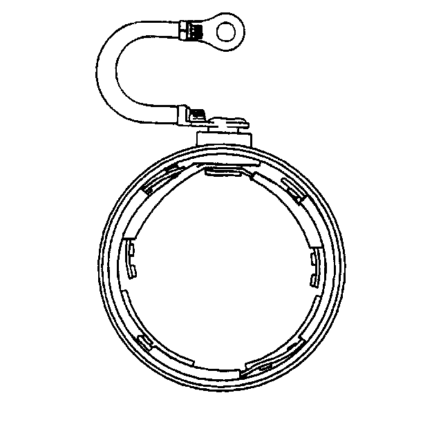
- Check the frame and field
assembly for grounds or opens.
| 3.1. | Inspect the field coil connections for opens between the field
terminal and the connection points for insulated brushes on the filed coil
straps. |
| 3.2. | Using a self-powered test lamp or ohmmeter, check for continuity
or grounds between the frame and the field terminal. |
| 3.3. | Replace the frame and field assembly that has grounds or opens. |
Armature Bearing Replacement
For 28-MT starter motor and components, refer to

Notice: Ball bearings that are removed from the armature must be replaced with
new bearings. The removal procedure causes internal damage to the bearings.
Removal Procedure
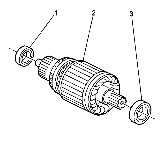
- Remove the armature bearings (1,3) and the armature (2) if replacing
the armature and bearings is necessary.
- Use a suitable bearing puller in order to remove the commutator
end or the drive end bearings from the armature assembly.
Installation Procedure

- Install the new commutator end and/or drive end bearings (1,3) to the
armature assembly (2) using a tube that bears only on the bearing inner race.
- Press on the bearing until the inner race bottoms out against
the shoulder of the armature shaft.
Center Support Bearing
Tools Required
Locally Fabricated Tool
Removal Procedure
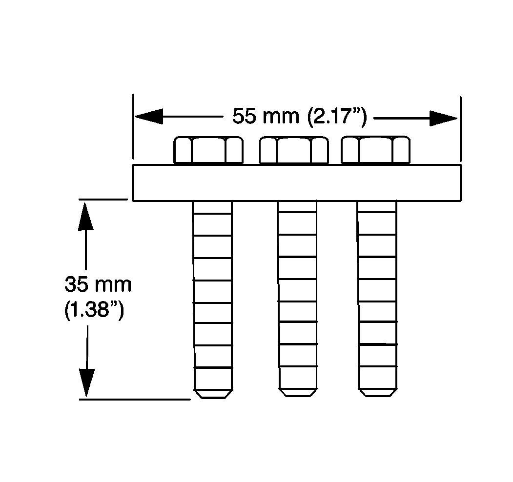
- Fabricate a tool for removing
the center support bearing using the dimensions shown.
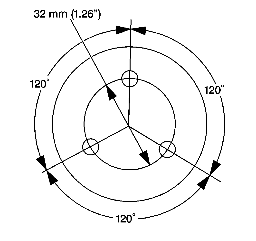
- Place the bolts in the
fabricated tool as shown.
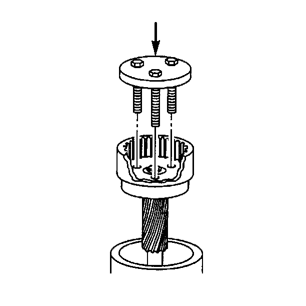
- Place the driveshaft in
a suitable support fixture.
Notice: Ball bearings that are removed from the armature must be replaced with
new bearings. The removal procedure causes internal damage to the bearings.
- Place the bolt ends of the locally fabricated tool through the access
holes in the wide end of the driveshaft.
- Squarely press the bearing off the surface on the center shaft.
Installation Procedure

- Install the new bearing
into the driveshaft using the locally fabricated tool that bears only on
the bearing inner race.
- Press on the bearing until the inner race bottoms out against
the shoulder on the driveshaft.
Drive End Housing Bushing
Removal Procedure
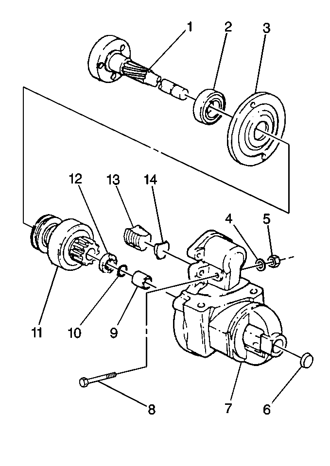
- Drive out the plug (6), if present, from inside the drive housing (7).
- Use a file to clean away remnants of the old stake and any metal
shavings in order to prepare for installation of a new plug.
- Using a suitable tool, press out the bushing (9).
Installation Procedure

- Using a suitable tool, press the new bushing (9) into the drive housing
(7) until the bushing is flush with the inside of the housing.
- Install a new plug (6), if used, in the drive housing.
- Stake the housing material over the plug at three places, equally
spaced.
Lubrication
Armature bearings and the driveshaft support bearing are permanently
lubricated. Do not add lubricant to these bearings. Using GM P/N 1960954
grease lubricant, or equivalent, lubricate the following areas during
assembly. Avoid using excessive lubrication.
| • | The drive end housing bushing in the drive housing |
| • | The pivot hole and working surface on the ends of the shift lever |
| • | The internal gear, shaft, and spline on the driveshaft |
Starter Inspection SD Series
Cleaning, Inspection and Electrical Tests
Notice: Do not clean the starter motor parts in a degreasing tank. Soaking parts
will dissolve the permanent lubrication and may damage the electrical
insulation. This will shorten starter motor life.
- Clean all parts by wiping with a clean cloth.
- Inspect the bushing or armature bearing fit in the drive end frame,
the lever housing, and the drive end frame housing. If the bushings or bearings
are damaged or worn, replace them.
| • | Lubricate the bushings before assembling the starter motor. Avoid
excessive lubrication. |
| • | Do not lubricate the roller bearings. They are permanently lubricated. |
- Inspect the armature for runout or scoring. Replace the armature
assembly if the condition of the armature shaft is questionable.
- Inspect the commutator for discolored or uneven conductors.
| • | Do not turn the commutator |
| • | Do not undercut the insulation |
| • | Clean the commutator with 240 grit emery cloth. Blow away any
copper dust present. If the commutator cannot be cleaned, replace the armature. |
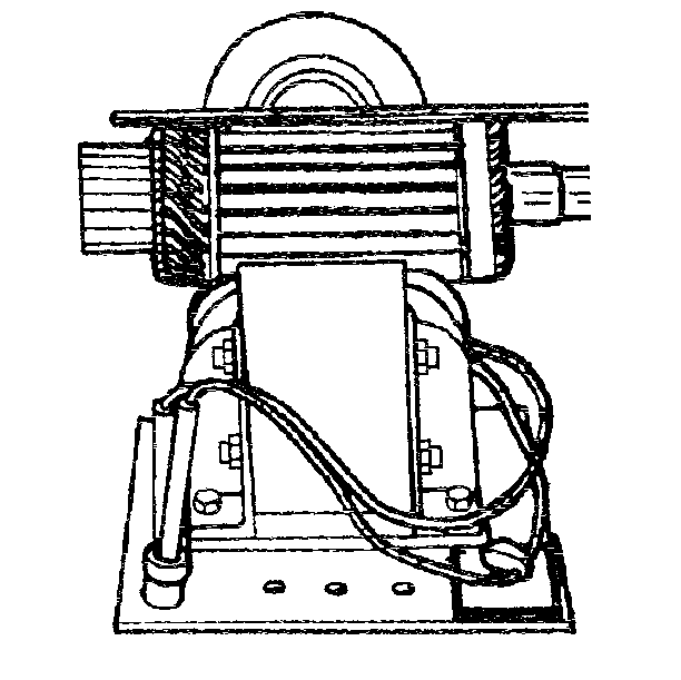
- Inspect the armature for
short circuits.
| • | Rotate the armature in a growler with a steel strip such as a
hacksaw blade. Hold the blade on the armature parallel to the shaft. The steel
strip will vibrate when it finds the short circuit. |
| • | Shorts between the commutator bars are sometimes produced by brush
dust or copper dust. |
- Inspect armature for opens.
| • | Look for loose connections where the conductors join the commutator
bars. |
| • | Poor connections cause arcing and burning of the commutator. |
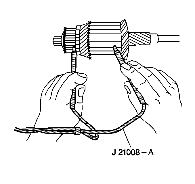
- Inspect the armature for
grounds using a self powered test lamp. If the test lamp lights when one
test probe is placed on the commutator and the other test lamp probe is
placed on the armature core shaft, the armature is grounded. Replace the
armature.
- Inspect the brushes for wear. If the brushes are worn to half
the size of a new brush, replace the assembly.
- Inspect the brush holders for dirt or damage. Make sure that the
brushes are not binding in the holders.
- Inspect the brush springs for distortion or discoloring. If the
springs are weak, bent, or discolored, replace the frame and field assembly.
- Inspect the field coils.
| • | Look for burned or damaged insulation, damaged connections or
loose poles. |
| • | If the conditions of the coils is doubtful, replace the field
and frame assembly. |
- Inspect the field coils for grounds.
| • | Connect a self-powered test lamp between the field frame and the
field connector. Make sure the brush ends do not contact the field frame. |
| • | If the test lamp lights, the field coils are grounded. Replace
the field and frame assembly. |
- Inspect the field coils for opens.
| • | Connect a self-powered lamp between the field connector and each
of the brushes. |
| • | If the test lamp does not light at both brushes, the field coils
are open. Replace the frame and field assembly |
- Inspect for field coils for shorts.
| • | Shorts are indicated by poor motor performance after everything
else has been checked out. |
| • | The coils cannot be replaced separately because of the integral
frame construction. The frame and field assembly must be replaced. |
- Inspect the drive assembly (clutch) by turning the drive pinion
in the cranking direction. If the drive pinion turns or slips in the cranking
direction, replace the over-running clutch assembly.
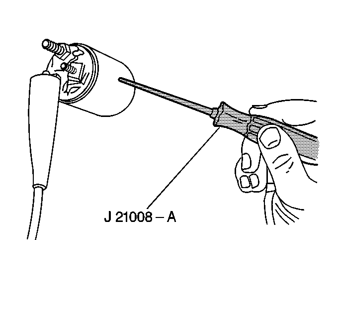
- Inspect the solenoid for
grounds using a self-powered 12 volt test lamp.
| 16.1. | Connect the test lamp between the BAT terminal and the case. The
lamp should not light (terminal should not be grounded). |
| 16.2. | Connect the test lamp between the S terminal and the case. Then
connect the test lamp between the M terminal and the S terminal or between
the M terminal and the case. The lamp should turn on. |
| 16.3. | If the solenoid does not pass these checks, replace it. |
Notice: To prevent overheating of the solenoid pull-in winding, do not leave
the winding energized for more than 15 seconds. The current draw will decrease
as the winding temperature increases.
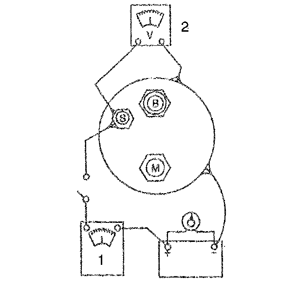
- Inspect the hold-in winding
and the pull-in winding.
| 17.1. | If the solenoid is not removed from the starter motor, the field
lead must be removed from the terminal on the solenoid before making these
tests. |
| 17.2. | To check both windings, connect an ammeter in series with a 12
volt battery and the switch terminal on the solenoid. Connect a carbon pile
across the battery. Ground the solenoid motor terminal. Adjust the voltage
to 10 volts and note the ammeter reading. It should be 60 to 85 amperes. |
| 17.3. | Note the ampere reading. A high reading indicates a shorted or
grounded winding, and a low reading indicates excessive resistance. |
| • | The resistance of the windings can be read directly using a digital
ohmmeter that can measure tenths of an ohm. |
| • | Coil resistance can be determined by dividing the voltage by the
current (amperes). |


