Cleaning Procedure
Notice: Do not subject a throttle body assembly which contains the following components
to an immersion cleaner or a strong solvent:
• Throttle position (TP) sensor • Idle air control (IAC) valve • Sealed throttle shaft bearings
Clean the throttle body bore and throttle valve plate on vehicle using a clean shop towel with GM Top Engine Cleaner, P/N 1052626 or AC-Delco Carburetor Tune-Up Conditioner, P/N X66P, or equivalent. Remove and disassemble the throttle body for cleaning if the deposits are excessive. After disassembly, clean the throttle body using a parts cleaner brush. DO NOT immerse the throttle body in any cleaning solvents.
Removal Procedure
- Disconnect the negative battery cable.
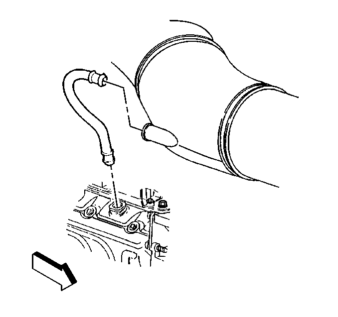
- Disconnect the crankcase vent tube from the rear intermediate duct.
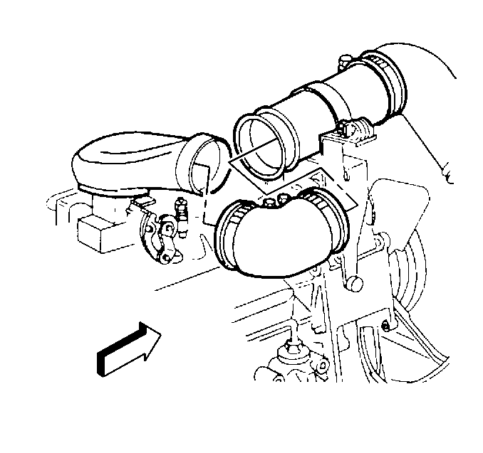
- Loosen the rear intermediate duct clamps and remove the duct.
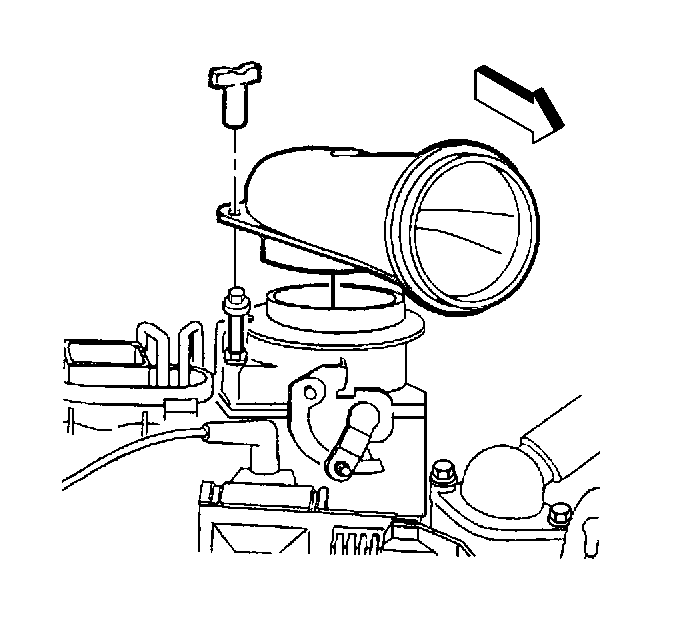
- Remove the air inlet duct fastener and the duct.
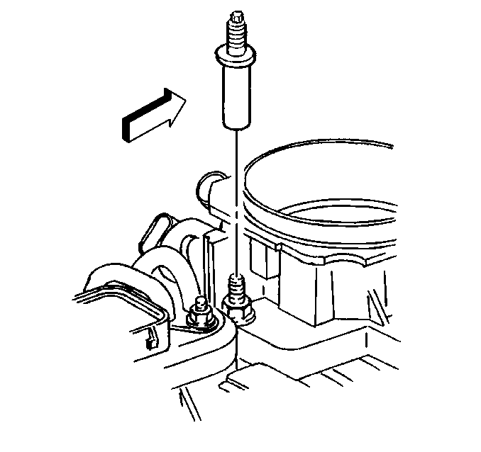
- Remove the air cleaner adapter stud.
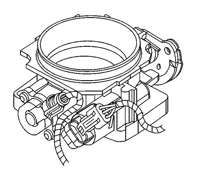
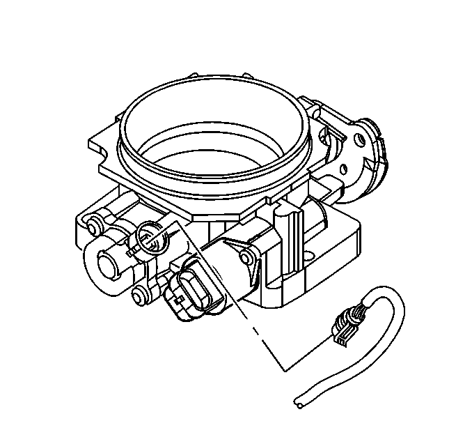
- Disconnect the IAC valve harness connector.
- Disconnect the TP sensor harness connector.
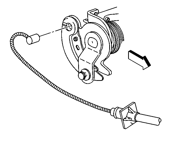
- Remove the accelerator cable from the throttle lever.
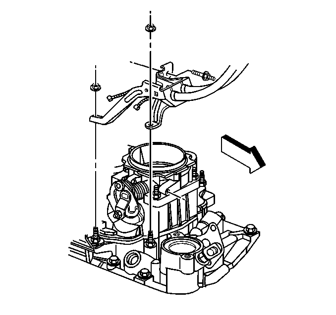
- Remove the accelerator cable bracket nuts and the bracket.
- Position bracket aside.
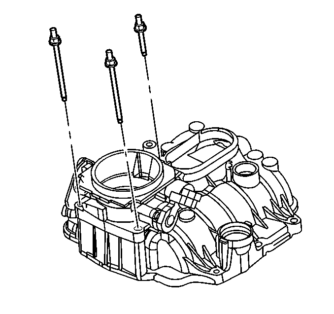
- Remove the throttle body retaining bolts or studs.
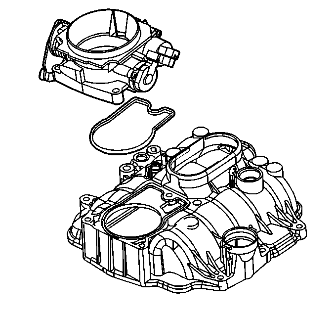
- Remove the throttle body assembly.
- Remove the flange seal.
- Discard the flange seal.
Caution: Unless directed otherwise, the ignition and start switch must be in the OFF or LOCK position, and all electrical loads must be OFF before servicing any electrical component. Disconnect the negative battery cable to prevent an electrical spark should a tool or equipment come in contact with an exposed electrical terminal. Failure to follow these precautions may result in personal injury and/or damage to the vehicle or its components.
Installation Procedure
- Clean the seal surface on the intake manifold.
- Install a new flange seal.
- Install the throttle body assembly.
- Install the throttle body assembly retaining bolt or stud.
- Install the accelerator cable bracket.
- Install the accelerator cable bracket nuts.
- Install the accelerator control cable.
- Connect the TP sensor harness connector.
- Connect the IAC valve harness connector.
- Install the air cleaner adapter stud.
- Install the air inlet duct and retaining nut.
- Install the rear intermediate duct.
- Connect the crankcase vent tube to the rear intermediate duct.
- Connect the negative battery cable.
- With the engine OFF, check to see that the accelerator pedal is not binding.

Notice: Use the correct fastener in the correct location. Replacement fasteners must be the correct part number for that application. Fasteners requiring replacement or fasteners requiring the use of thread locking compound or sealant are identified in the service procedure. Do not use paints, lubricants, or corrosion inhibitors on fasteners or fastener joint surfaces unless specified. These coatings affect fastener torque and joint clamping force and may damage the fastener. Use the correct tightening sequence and specifications when installing fasteners in order to avoid damage to parts and systems.

Tighten
Tighten the throttle body attaching bolt or stud to 9 N·m
(80 lb in).


Important: Make sure the accelerator control linkage does not hold the throttle open. Refer to Accelerator Controls Cable Replacement .


Notice: Use the correct fastener in the correct location. Replacement fasteners must be the correct part number for that application. Fasteners requiring replacement or fasteners requiring the use of thread locking compound or sealant are identified in the service procedure. Do not use paints, lubricants, or corrosion inhibitors on fasteners or fastener joint surfaces unless specified. These coatings affect fastener torque and joint clamping force and may damage the fastener. Use the correct tightening sequence and specifications when installing fasteners in order to avoid damage to parts and systems.

Tighten
Tighten the nut to 8 N·m (72 lb in).

Tighten
Tighten the nut to 2.5 N·m (22 lb in).


| 15.1. | Depress the pedal to the floor. |
| 15.2. | Release the accelerator pedal. |
