GM Service Manual Online
For 1990-2009 cars only

Evaporative Emission Control System Operation Description Non-Enhanced

EVAP Control System (Purpose)


Object Number: 245919  Size: MF
(1)EVAP Canister Purge Hose
(2)EVAP Canister Purge Solenoid
(3)EVAP Canister Purge Solenoid Ground Circuit
(4)EVAP Canister Purge Solenoid Ignition Feed Circuit
(5)Intake Manifold
(6)Air/Water Separator
(7)Fuel Tank Filler Neck
(8)Fuel Tank Vent
(9)Fuel Tank
(10)EVAP Canister

The Evaporative Emission (EVAP) control system limits the fuel vapors from escaping into the atmosphere. The EVAP system transfers the fuel vapor from the sealed fuel tank (9) to an activated carbon (charcoal) storage device known as the EVAP canister (10). The EVAP canister stores the fuel vapors until the engine is able to use the extra fuel vapor.

When the engine is able to use the extra fuel vapor, the intake air flow (5) purges the fuel vapor from the carbon element. After the fuel vapor has been purged from the carbon element, the normal combustion process consumes the fuel vapors.

The fuel tank is sealed with a fuel cap that is not normally vented to the atmosphere. The fuel tank cap has a safety valve which allows for both pressure and vacuum relief.
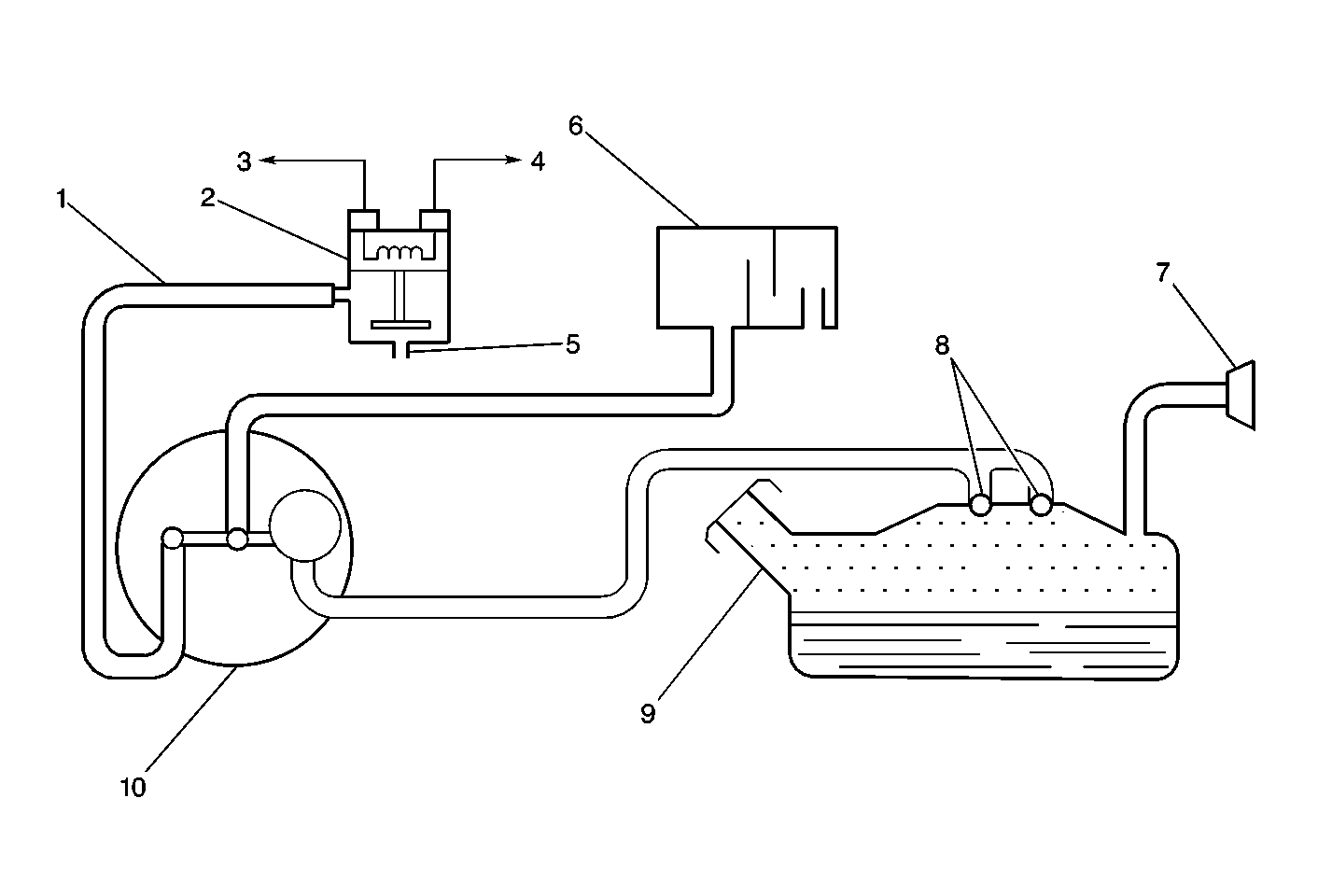
EVAP Control System (Operation)


Object Number: 245919  Size: MF
(1)EVAP Canister Purge Hose
(2)EVAP Canister Purge Solenoid
(3)EVAP Canister Purge Solenoid Ground Circuit
(4)EVAP Canister Purge Solenoid Ignition Feed Circuit
(5)Intake Manifold
(6)Air/Water Separator
(7)Fuel Tank Filler Neck
(8)Fuel Tank Vent
(9)Fuel Tank
(10)EVAP Canister

Fuel vapors from the fuel tank (9) purge and flow into the EVAP canister (10) where the carbon absorbs these vapors. The canister purges when the engine is able to use extra fuel vapor. A vacuum source is applied to the EVAP canister and the canister draws in fresh air through the top of the canister. The air mixes with the fuel vapor and the mixture is drawn into the intake manifold (5) to be consumed in the normal combustion process.

While the EVAP canister is purging, fresh air is drawn in through the air inlet at the top of the canister. Air flows to the bottom of the canister and forces the vapors into the purge tube(1).

The EVAP system in some applications uses an electrically controlled solenoid known as the EVAP Canister Purge Solenoid (2) to cycle the vacuum to the EVAP canister. The VCM cycles the EVAP canister purge solenoid when the engine coolant temperature is greater than 45°C (113°F) or the Short Term Fuel Trim counter is less than 122 counts.

Evaporative (EVAP) System Canister


Object Number: 12722  Size: LH
(1)Purge Line
(2)Vapor From Fuel Tank
(3)Air

The evaporative system canister, filled with charcoal pellets, stores the fuel vapors from the fuel tank. The engine vacuum purges the vapor canister during normal driving.

Evaporative Canister Purge Solenoid Valve


Object Number: 12726  Size: SH

When energized, the evaporative Canister Purge Valve allows the fuel vapor to flow from the EVAP canister to the engine. The normally closed valve is pulse width modulated by the Control Module in order to precisely control the vapor flow. The valve opens during the Enhanced Evaporative Diagnostic Test in order to create a vacuum in the fuel tank and then closed in order to seal the system.

EVAP Air Separator


Object Number: 245607  Size: MH

The Air Separator is connected to the EVAP Canisters inlet tube by a hose. It is open to the atmosphere. A series of baffles prevents water droplets from entering the EVAP Canisters fresh air inlet tube.

Evaporative System Service Port


Object Number: 21046  Size: SH

The Evaporative System Service Port is located in the evaporative hose located between the purge solenoid and the canister. The service port is identified by a green colored cap.