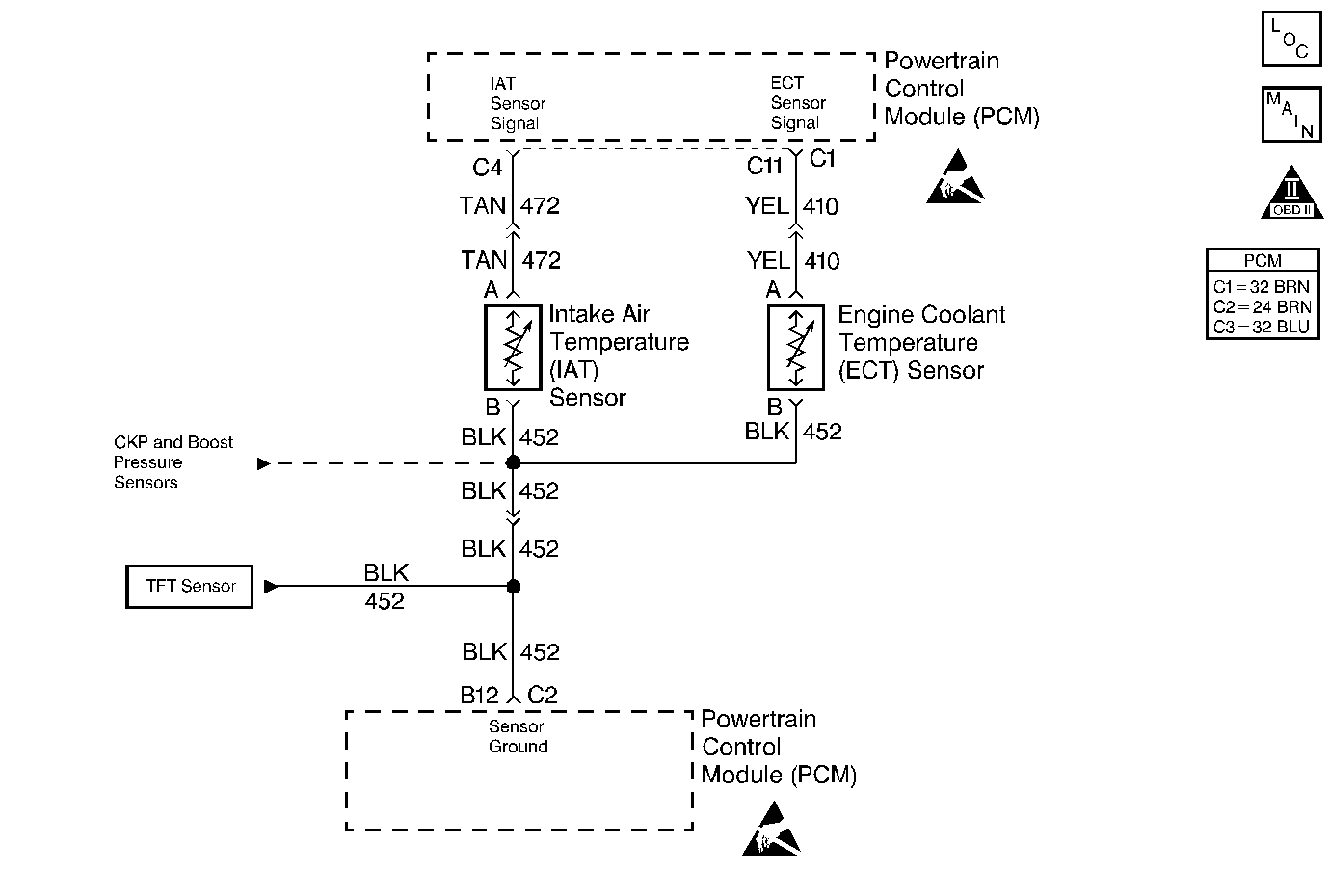
Circuit Description
The Intake Air Temperature (IAT) sensor is a thermister that controls the signal voltage to the PCM. When the air is cold, the sensor resistance is high, therefore the PCM will see a high signal voltage. As the air warms, the sensor resistance becomes less and the voltage drops.
Conditions for Setting the DTC
| • | The engine coolant temperature is less than 42.5°C (109°F). |
| • | The intake air temperature is greater than or equal to 151°C (304°F). |
| • | The conditions were met for 2 seconds. |
Action Taken When the DTC Sets
| • | The PCM illuminates the Malfunction Indicator Lamp (MIL) on the second consecutive drive trip the diagnostic runs and fails. |
| • | The PCM records the operating conditions at the time the diagnostic fails. The first time the diagnostic fails, the Failure Records store this information. If the diagnostic reports a failure on the second consecutive drive trip, the Freeze Frame records the operating conditions at the time of failure and updates the Failure Records. |
Conditions for Clearing the MIL/DTC
| • | The PCM will turn the MIL off after three consecutive trips without a fault condition. |
| • | A History DTC will clear after forty consecutive warm-up cycles during which the diagnostic does not fail (the coolant temperature has risen 5°C (40°F) from the start up coolant temperature and the engine coolant temperature exceeds 71°C (160°F) during that same ignition cycle). |
| • | Use of a Scan Tool will clear the DTC codes. |
Diagnostic Aids
Check harness routing for a potential short to ground in the signal circuit. Scan Tool displays intake air temperature in degrees centigrade. Refer to Symptoms . A skewed sensor could result in poor driveability complaints. Refer to Temperature Versus Resistance .
Test Description
The number(s) below refer to the step number(s) on the Diagnostic Table.
-
This step determines if P0112 is a hard failure or an intermittent condition.
-
This test will determine if the PCM can recognized an open sensor.
-
This step will determine if the problem is a malfunctioning PCM or the signal wire is shorted to ground. The normal resistance across the IAT sensor connector harness is 4000-5000 ohms.
Step | Action | Value(s) | Yes | No |
|---|---|---|---|---|
1 |
Important: Before clearing any DTCs, use the Scan Tool Capture Info to save freeze frame and failure records for reference, as the Scan Tool loses data when using the Clear Info function. Was the Powertrain On-Board Diagnostic (OBD) System Check performed? | -- | ||
Is the IAT display greater than or equal to the specified value? | 151°C (303°F) | |||
Does the IAT display a temperature colder than or equal to the specified value? | -30°C (-22°F) | |||
Is the resistance at the specified value? | Infinite | |||
5 | The DTC is intermittent. If no additional DTCs are stored, refer to Diagnostic Aids. If any additional DTCs were stored, refer to those table(s). Are there additional DTCs stored? | -- | Go to the Applicable DTC Table | Go to Diagnostic Aids |
6 | Repair the short to ground in the IAT signal circuit. Is the action complete? | -- | -- | |
7 | Replace the IAT sensor. Refer to Engine Coolant Temperature Sensor Replacement . Is the action complete? | -- | -- | |
8 | Replace the PCM. Important: The new PCM must be programmed. Refer to Powertrain Control Module Replacement/Programming . Is the action complete? | -- | -- | |
9 |
Does the Scan Tool indicate the diagnostic Passed? | -- | ||
10 | Does the Scan Tool display any additional undiagnosed DTCs? | -- | Go to the Applicable DTC Table | System OK |
