GM Service Manual Online
For 1990-2009 cars only
Makes
🢒
GMC_Truck
🢒
1998
🢒
GMC P42 Commercial Chassis
🢒
Brakes
🢒
Park Brake
🢒 Park Brake System Schematics
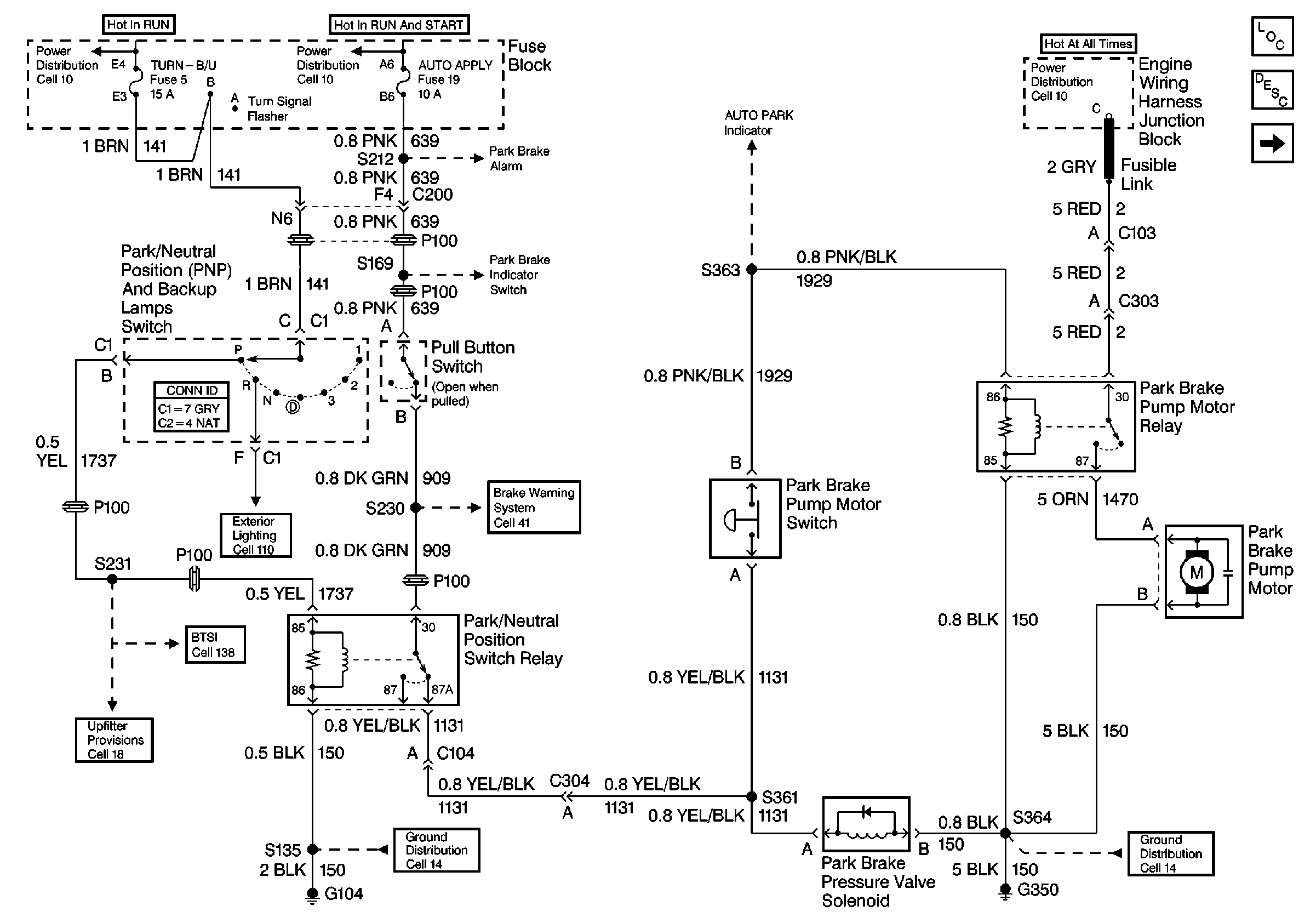
Figure
1:
Cell 41: Park Brake Pump Control
Park Brake System Components
Electric/Auto Park Circuit Description P32 Upfitter
Cell 41: AUTO PARK Warning Circuit
Cell 138: P32 BTSI Circuit
Cell 18: Door Ajar Switch, Dome Lamp, Park Accessory, Low Current, and Horns
Cell 10: Ignition Switch and Fuse Block
Cell 41: Park Brake Alarm
Park Brake System Connector End Views
Cell 41: Auto Apply Relays
Shift Lock Control Schematics
Cell 10: Battery, Starter and Junction Block
Cell 14: G350, G400, G401, and G402
Cell 14: G104 [L29]
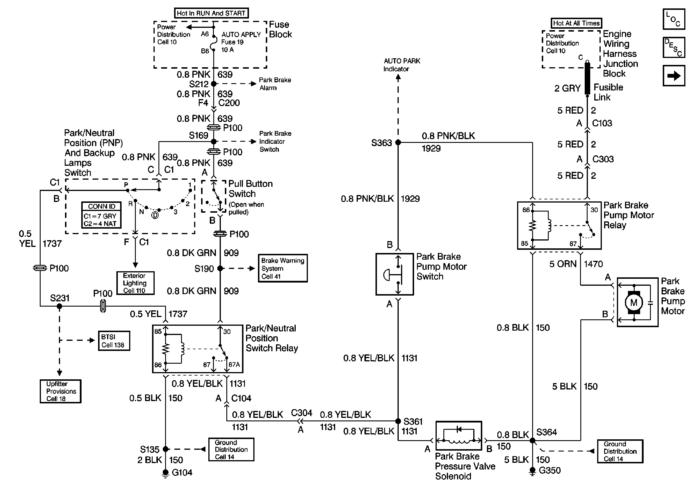
Figure
2:
Cell 41: AUTO PARK Warning Circuit
Park Brake System Components
Electric/Auto Park Circuit Description P32 Upfitter
Cell 41: Park Brake Alarm
Cell 41: Park Brake Pump Control
Cell 10: Ignition Switch and Fuse Block
Cell 41: Park Brake Alarm
Handling ESD Sensitive Parts Notice
Cell 14: G108 [L29]
Cell 41: Park Brake Pump Control
Figure
3:
Cell 41: Park Brake Alarm
Park Brake System Components
Electric/Auto Park Circuit Description P32 Upfitter
Cell 41: Park Brake Pump Control
Cell 10: Ignition Switch and Fuse Block
Cell 41: Park Brake Pump Control
Cell 41: Brake Warning System - US
Cell 41: Brake Warning System - Canada
Cell 41: Brake Warning System - Export
Cell 14: G200
Cell 14: G350, G400, G401, and G402
Figure
4:
Cell 41: Park Brake Pump Control
Park Brake System Components
Electric/Auto Park Circuit Description P32 Upfitter
Cell 41: Park Brake Alarm
Cell 138: P32 BTSI Circuit
Cell 18: Door Ajar Switch, Dome Lamp, Park Accessory, Low Current, and Horns
Cell 10: Ignition Switch and Fuse Block
Cell 41: Park Brake Alarm
Park Brake System Connector End Views
Cell 41: Auto Apply Relays
Shift Lock Control Schematics
Cell 10: Battery, Starter and Junction Block
Cell 14: G350, G400, G401, and G402
Cell 14: G104 [L29]