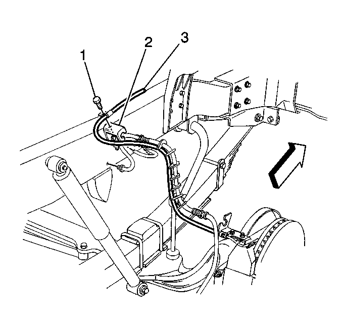
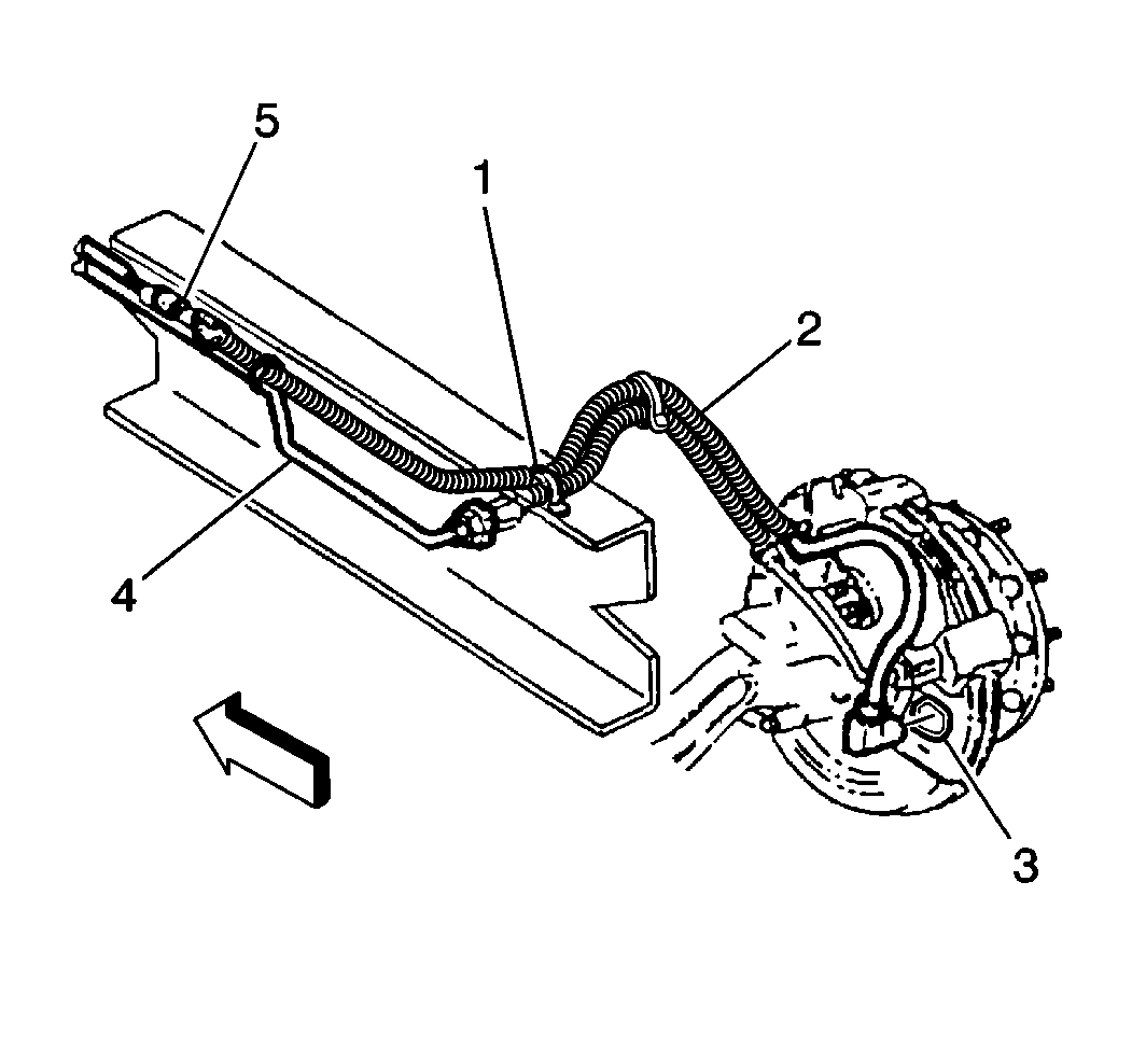
For 1990-2009 cars only
Wheel Speed Sensor Replacement Independent Front Suspension
Removal Procedure
- Disconnect the electrical connector (5).
- Remove the nylon straps (1) retaining the sensor wire (2) to the brake line (4). Note the location of the straps.
- Remove the wheel speed sensor from the bore.
- Remove the speed sensor retaining clip (3). The clip may come out with the wheel speed sensor or stay in the bore. If the sensor retaining clip is still functioning correctly, save it for reinstallation. If the sensor retaining clip is not functioning correctly, replace the sensor retaining clip.

Installation Procedure
Important: You may have to use the wire retainers from the old wheel speed sensor wire on the new sensor. Do not damage the new wire when installing the retainers.
- Install the wheel speed sensor and the retaining clip (3) into the bore.
- Secure the sensor wire (2) to the brake line (4) with a wire tie (1) in the location noted during removal.
- Connect the electrical connector (5).
Important: Insert the sensor and the retaining clip (3) completely into the bore. The face of the sensor should contact the tone ring. The clip should stop at the retaining tabs.

Wheel Speed Sensor Replacement I-Beam front Suspension
Removal Procedure
- Disconnect the wheel speed sensor electrical connector (5).
- Remove the wheel speed sensor from the bore (3).
- Remove the wheel speed sensor harness clip bracket (3).

Installation Procedure
- Install the wheel speed sensor and the retaining clip into the bore (3).
- Secure the sensor wire to the brake line with a wire tie in the location noted during removal (1).
- Connect the electrical connector (5).

Important: Insert the sensor and the retaining clip completely into the bore. The face of the sensor should contact the tone ring. The clip should stop at the retaining tabs.
