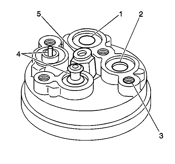
For 1990-2009 cars only
Removal Procedure
Tools Required
| • | J 9553-01 O-Ring Remover |
| • | J 5403 Snap Ring Pliers |
- Recover the refrigerant.
- Disconnect the electrical connector from the switch (4) in the rear head of the compressor.
- Remove the switch retaining ring using the J 5403 .
- Remove the switch (4) from the compressor.
- Remove the old O-ring seal from the switch cavity using the J 9553-01 .

Installation Procedure
Tools Required
J 5403 Snap Ring Pliers
- If you are reinstalling an existing control switch in the compressor, use a new O-ring and a new retainer ring. An O-ring and a retainer ring is included in a new switch kit.
- Inspect the switch cavity and the O-ring groove in the rear head for dirt or for foreign material.
- Lubricate the new O-ring using clean refrigerant oil.
- Install the new O-ring into the groove in the switch cavity.
- Lubricate the control switch housing using clean refrigerant oil.
- Install the switch (4) into the switch cavity until the switch bottoms out in the cavity.
- Using the J 5403 , install the switch retaining ring.
- Ensure that the retaining ring is properly seated in the switch cavity retaining groove.
- Leak test according to the bench test procedure.

Clean the components as necessary.
Ensure that the high point of the curved sides is adjacent to the switch housing.
