Distributor Replacement Procedure A
Removal Procedure A
Notice: If the distributor is removed from the engine, it can be re-installed
using Procedure A as long as the crankshaft has not rotated from the original
position. If the intake manifold, the cylinder head, the crankshaft, the camshaft,
the timing gear, or the complete engine was removed or replaced, Procedure
B must be followed in order to correctly install the distributor. A DTC code
may also indicate an incorrectly installed distributor and engine or distributor
damage may occur. Procedure B must then be used.
- Turn the ignition switch to the OFF position.
- Disconnect the spark plug and coil leads from the distributor
cap.
- Disconnect the three wire Hall-effect switch connector from the
base of the distributor.
- Remove the two screws holding the distributor cap to the housing.
- Remove the distributor cap. For proper alignment during reinstallation:
| 5.1. | Using a grease pencil, mark the position of the rotor segment
in relation to the distributor housing. Identify the mark with a 1. |
| 5.2. | Using a grease pencil, mark the distributor housing and intake
manifold. |
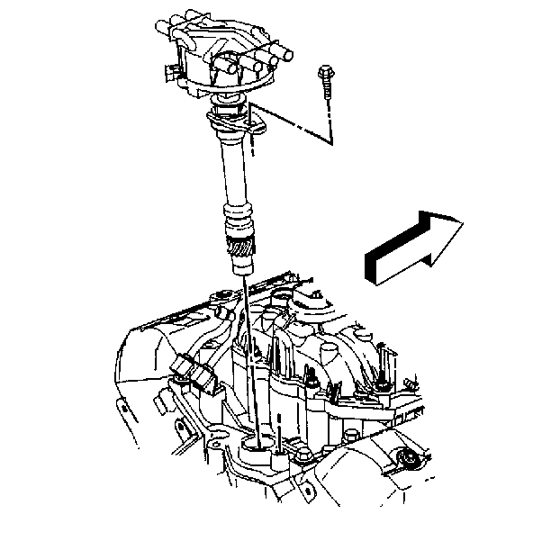
- On a 4.3L engine:
| 6.1. | Remove the mounting clamp hold down bolt. |
| 6.2. | Remove the distributor. Note that the rotor will move counterclockwise
42 degrees. |
| 6.3. | Note the position of the rotor segment by marking the base of
the distributor with a 2 in order to aid proper alignment during installation. |
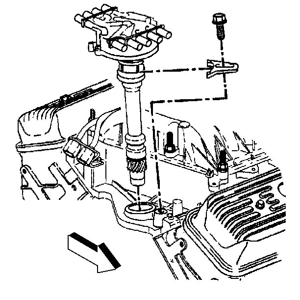
- On a 5.7L engine:
| 7.1. | Remove the mounting clamp hold down bolt. |
| 7.2. | Remove the distributor. Note that the rotor will move counterclockwise
42 degrees. |
| 7.3. | Note the position of the rotor segment by marking the base of
the distributor with a 2 in order to aid proper alignment during installation. |
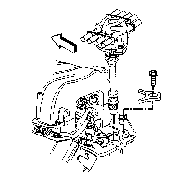
- On a 7.4L engine:
| 8.1. | Remove the ignition coil. |
| 8.2. | Remove the mounting clamp hold down bolt. |
| 8.3. | Remove the distributor. Note that the rotor will move counterclockwise
42 degrees. |
| 8.4. | Note the position of the rotor segment by marking the base of
the distributor with a 2 in order to aid proper alignment during installation. |
Installation Procedure A
- If the distributor is being replaced and not repaired:
| 1.1. | Remove the new distributor cap. |
| 1.2. | Using a grease pencil, place two marks on the new distributor
housing in the same location as the two marks on the original housing. |
- When installing the distributor, align the rotor segment with
the number 2 mark on the base of the distributor.
- Guide the distributor into place. Make sure the grease pencil
marks on the distributor housing and intake manifold are in line.
| 3.1. | As the distributor is being installed, the rotor moves clockwise
42 degrees. |
| 3.2. | Once the distributor is completely seated, the rotor segment should
be aligned with the number 1 mark on the base. |
- If the rotor is not aligned with the number 1 mark, the gear teeth
of the distributor and the camshaft have not meshed properly.
| 4.1. | Remove the distributor. |
| 4.2. | Repeat the procedure starting at step two. |
Notice: Use the correct fastener in the correct location. Replacement fasteners
must be the correct part number for that application. Fasteners requiring
replacement or fasteners requiring the use of thread locking compound or sealant
are identified in the service procedure. Do not use paints, lubricants, or
corrosion inhibitors on fasteners or fastener joint surfaces unless specified.
These coatings affect fastener torque and joint clamping force and may damage
the fastener. Use the correct tightening sequence and specifications when
installing fasteners in order to avoid damage to parts and systems.
- Install the distributor
cap and mounting screws.
Tighten
Tighten the distributor cap screws to 5 N·m (40 lb in).

- On a 4.3L engine, install
the distributor hold down bolt.
Tighten
Tighten the distributor hold down bolt to 27 N·m (20 lb ft).

- On a 5.7L engine, install
the distributor mounting clamp and hold down bolt.
Tighten
Tighten the distributor hold down bolt to 27 N·m (20 lb ft).

- On a 7.4L engine, install
the distributor mounting clamp and hold down bolt.
Tighten
Tighten the distributor hold down bolt to 27 N·m (20 lb ft).
- Connect the three wire Hall-effect switch connector to the base
of the distributor.
- Install the ignition coil.
- Connect the spark plug and coil leads to the distributor.
- Check the installation. If the CHECK ENGINE lamp is illuminated
and a DTC P1345 is found, refer to Installation Procedure B for proper
distributor installation.
Distributor Replacement Procedure B
Removal Procedure B
- Bring the engine to Top Dead Center of cylinder number 1. Make
sure the cylinder is on the compression stroke.
- Remove the distributor cap screws and cap in order to expose the
rotor.
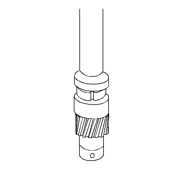
- Align the pre-drilled indent hole in the
distributor driven gear with the white painted alignment line on the lower
portion of the shaft housing.
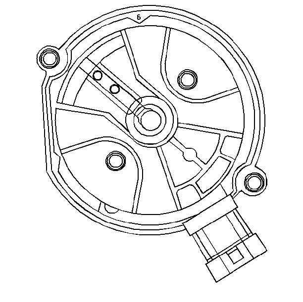
- On a 4.3L engine, make sure the rotor segment
points to the cap hold area as shown.
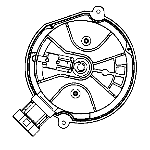
- On a 5.7L or 7.4L engine, make sure the
rotor segment points to the cap area as shown.
- Using a long screwdriver, align the oil pump drive shaft in the
engine in the mating drive tab in the distributor.
- Guide the distributor into place. Make sure the spark plug towers
are perpendicular to the center line of the engine.
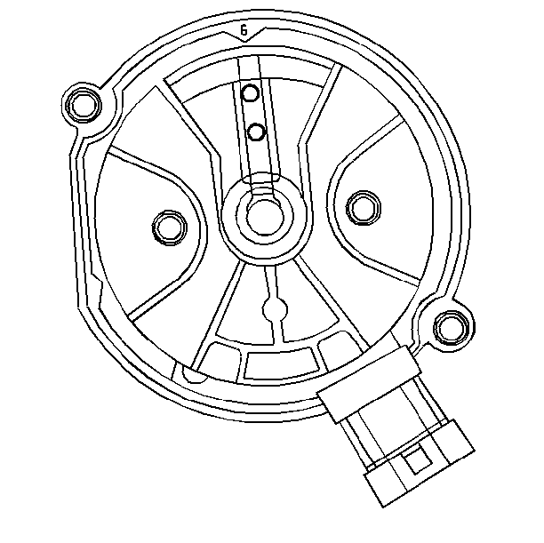
- On a 4.3L engine, once the distributor
is fully seated, the rotor segment should align with the pointer cast into
the distributor base.
| • | The 6 cast into the pointer indicates the distributor is for a
six cylinder engine. |
| • | If the rotor segment does not come within a few degrees of the
pointer, the gear mesh between the distributor and camshaft may be misaligned. |
| • | Repeat the procedure if proper alignment is not achieved. |
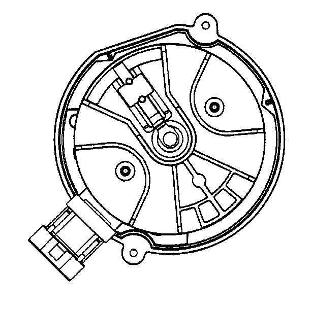
- On a 5.7L or 7.4L engine, once the distributor
is fully seated, the rotor segment should align with the pointer cast into
the distributor base.
| • | The 8 cast into the pointer indicates the distributor is for a
eight cylinder engine. |
| • | If the rotor segment does not come within a few degrees of the
pointer, the gear mesh between the distributor and camshaft may be misaligned. |
| • | Repeat the procedure if proper alignment is not achieved. |
Installation Procedure B
Notice: Use the correct fastener in the correct location. Replacement fasteners
must be the correct part number for that application. Fasteners requiring
replacement or fasteners requiring the use of thread locking compound or sealant
are identified in the service procedure. Do not use paints, lubricants, or
corrosion inhibitors on fasteners or fastener joint surfaces unless specified.
These coatings affect fastener torque and joint clamping force and may damage
the fastener. Use the correct tightening sequence and specifications when
installing fasteners in order to avoid damage to parts and systems.
- Install the distributor
cap and mounting screws.
Tighten
Tighten the distributor cap screws to 5 N·m (40 lb in).

- On a 4.3L engine, install the distributor
hold down bolt.
Tighten
Tighten the distributor hold down bolt to 27 N·m (20 lb ft).

- On a 5.7L engine, install the distributor
mounting clamp and hold down bolt.
Tighten
Tighten the distributor hold down bolt to 27 N·m (20 lb ft).

- On a 7.4L engine, install the distributor
mounting clamp and hold down bolt.
Tighten
Tighten the distributor hold down bolt to 27 N·m (20 lb ft).
- Connect the three wire Hall-effect switch connector to the base
of the distributor.
- Connect the spark plug and coil leads to the distributor cap.
- Check the installation. Refer to Installation Procedure B if the
CHECK ENGINE lamp is illuminated and a DTC P1345 is found.


