Steering Gear Adjustments Saginaw - 710 Model
Adjustment Procedure
Tools Required
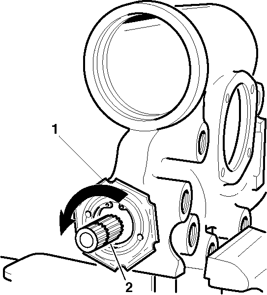
- Drain the oil from the
steering gear by rotating the steering gear completely several times.
- Turn the stub shaft (1) from the right wheel stop to the
left wheel stop while counting the number of turns.
- Rotate the stub shaft (1) back half the number of turns
to the center position.
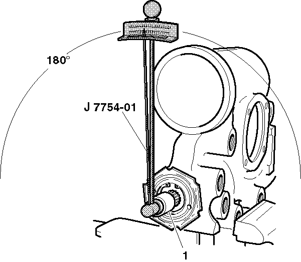
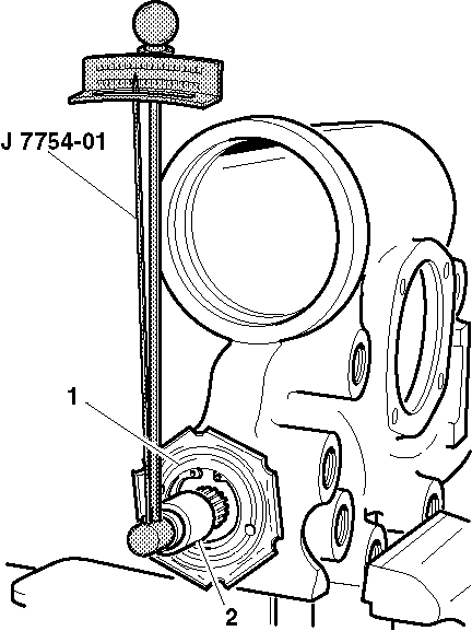
- Place J 7754-01
and a deepwell ¾ inch
12 point socket (1) over the stub shaft in order to check the total
preload torque by rotating J 7754-01
through a 180 degree arc either side of the center.
- Record the highest reading while turning J 7754-01
back over the center position.
- Turn the stub shaft ½ turn (180 degrees)
right or left from the center.
- Install J 7754-01
vertically on the stub shaft.
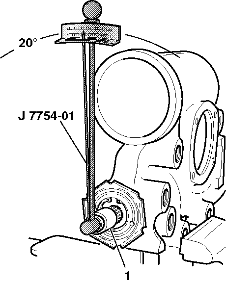
- Turn J 7754-01
20 degrees to the left or the
right of the vertical position.
- Record the reading while turning J 7754-01
back to the vertical position.
- Subtract this reading from the reading in step 5.
- If the reading in step 5 is 0.23 N·m (2 lb in),
then the steering gear is adjusted properly. If the reading in step 5
is less than 0.23 N·m (2 lb in) proceed with
the following adjustments:
| 11.1. | If the reading in step 5 is at least 0.23 N·m
(2 lb in) and not more than 1.13 N·m (10 lb in),
the steering gear is adjusted properly. Proceed to steps 12 through 16. |
| 11.2. | If the reading in step 5 is less than 0.23 N·m
(2 lb in) or more than 1.13 N·m (10 lb in),
proceed to step 12 through 23. |
- Loosen the coupling shield retainer and the lock nut with the
steering gear centered.
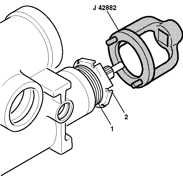
- Turn the adjuster nut
assembly (1) clockwise using J 42882
. Torque the adjuster nut assembly (1) to 28-31 N·m
(21-23 lb ft) and back off 15-25 degrees.
- Tighten the coupling shield and lock nut (2). Stabilize
the adjuster nut assembly (1) while tightening the coupling shield
and lock nut (2).
- Turn the stub shaft 2 turns right or left from the center position.
- Install J 7754-01
near vertical. Record the torque reading.
The torque reading should be 1.60 N·m (14 lb in)
while turning J 7754-01
in an arc 20 degrees left or right of the vertical position.
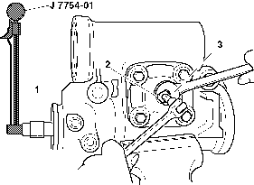
- With the steering gear
in the center position, loosen the preload adjuster nut (2). Ensure
the adjusting screw is backed out counterclockwise all the way.
- Turn the adjuster screw clockwise ½ turn. This prevents
the pitman shaft from bottoming out of the side cover.
- Place J 7754-01
in the vertical position in order to check the preload.
- Move J 7754-01
90 degrees to the left or the right of the center position. Record
the highest torque reading while moving J 7754-01
back to the center position.
- Tighten the adjuster screw clockwise until the torque reading
is 0.68-1.13 N·m (6-10 N·m) higher than
the reading taken in the previous step.
- Tighten the preload adjuster nut (2) to 90 N·m
(66 N·m). Ensure the adjuster screw does not turn during tightening.
- Reinspect the preload after tightening the preload adjuster nut (2).


