Wheel Bearing Adjustment Independent
Notice: Never preload the front wheel bearings. Damage can result by the steady load on the roller ends that comes from preloading.
Important:
• Adjust the front wheel bearings correctly in order to ensure the
front suspension functions properly. • The bearings must be a slip fit on the spindle. • Lubricate the bearings in order to ensure that the roller bearings
will roll and not skid. • The spindle nut must have a free-running fit on the spindle threads.
- Raise the vehicle. Support the vehicle with suitable safety stands under the lower control arms.
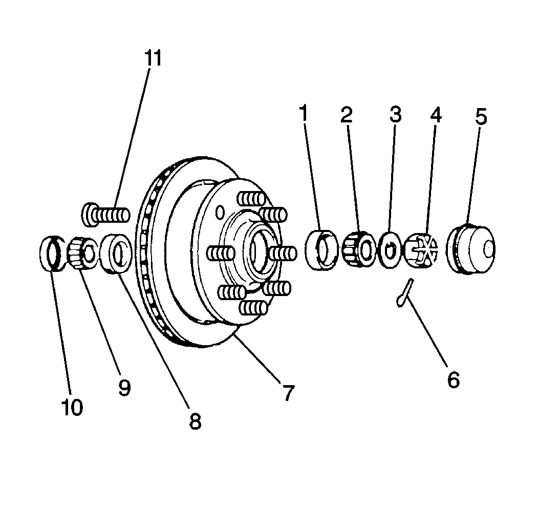
- Remove the dust cap (5) from the hub/rotor (7).
- Remove the cotter pin (6).
- Back the nut off to a just loose position.
- Finger tighten the nut.
- Back off the nut until the hole in the spindle lines up with a slot on the nut.
- Install a new cotter pin. Make sure the cotter pin ends do not interfere with the dust cap.
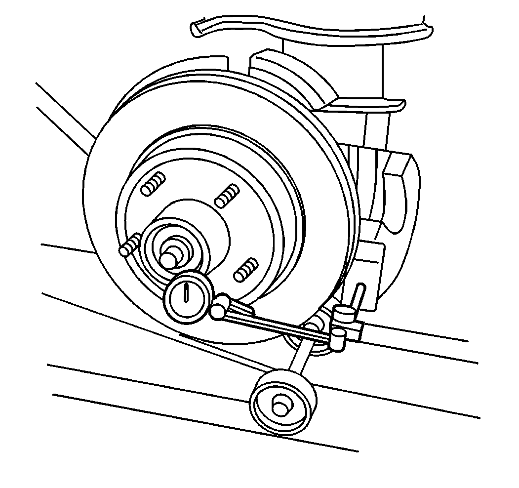
- Measure the endplay in the hub/rotor assembly. This measurement should be between 0.03 mm (0.0012 in), and 0.13 mm (0.005 in) when properly adjusted.
- Install the dust cap on the hub/rotor.
- Install the tire and wheel assembly, if removed.
- Lower the vehicle.

Notice: Use the correct fastener in the correct location. Replacement fasteners must be the correct part number for that application. Fasteners requiring replacement or fasteners requiring the use of thread locking compound or sealant are identified in the service procedure. Do not use paints, lubricants, or corrosion inhibitors on fasteners or fastener joint surfaces unless specified. These coatings affect fastener torque and joint clamping force and may damage the fastener. Use the correct tightening sequence and specifications when installing fasteners in order to avoid damage to parts and systems.
Tighten
Tighten the nut to 16 N·m (12 lb ft), while
turning the wheel and tire assembly forward by hand. This will seat the bearings.
Important: Do not back the nut off more than ½ of a nut flat.

Wheel Bearing Adjustment I-Beam
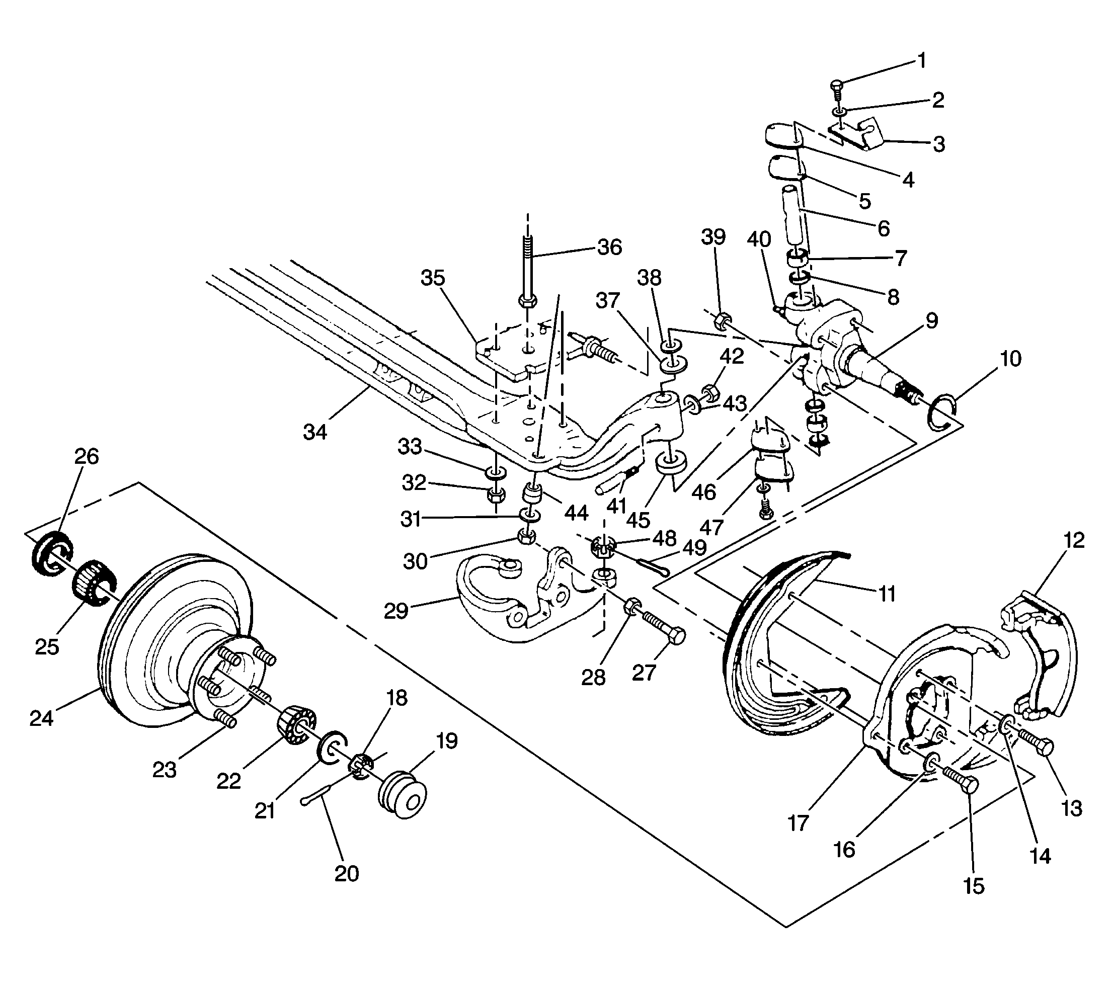
For the front axle, hub and components, refer to
Front Axle, Steering Knuckle, Hub, and Components (I-Beam Suspension)

Notice: Never preload the front wheel bearings. Damage can result by the steady load on the roller ends that comes from preloading.
Important:
• Adjust the front wheel bearings correctly in order to ensure the
front suspension functions properly. • The bearings must be a slip fit on the spindle. • Lubricate the bearings in order to ensure that the roller bearings
will roll and not skid. • The spindle nut must have a free-running fit on the spindle threads.
- Raise the vehicle. Support the vehicle with suitable safety stands under the lower control arms.
- Remove the retainer cap.
- Remove the cotter pin.
- Back the nut off one flat.
- Measure the endplay in the hub/rotor. This measurement should be between 0.013-0.20 mm (0.0005-0.008 in) when properly adjusted.
- Install the retainer cap.
- Lower the vehicle.
- Check the front wheel alignment. Refer to Wheel Alignment Specifications in Wheel Alignment.
Notice: Use the correct fastener in the correct location. Replacement fasteners must be the correct part number for that application. Fasteners requiring replacement or fasteners requiring the use of thread locking compound or sealant are identified in the service procedure. Do not use paints, lubricants, or corrosion inhibitors on fasteners or fastener joint surfaces unless specified. These coatings affect fastener torque and joint clamping force and may damage the fastener. Use the correct tightening sequence and specifications when installing fasteners in order to avoid damage to parts and systems.
Tighten
Tighten the nut (4) to 16 N·m (12 lb ft),
while turning the wheel and tire assembly, or the hub/rotor, forward by hand.
This will seat the bearings.
| • | If the hole in the spindle lines up with the slot in the nut, insert the cotter pin. |
| • | If these do not line up, back off the nut until these line up. Do not back off the nut more than one additional flat. |

