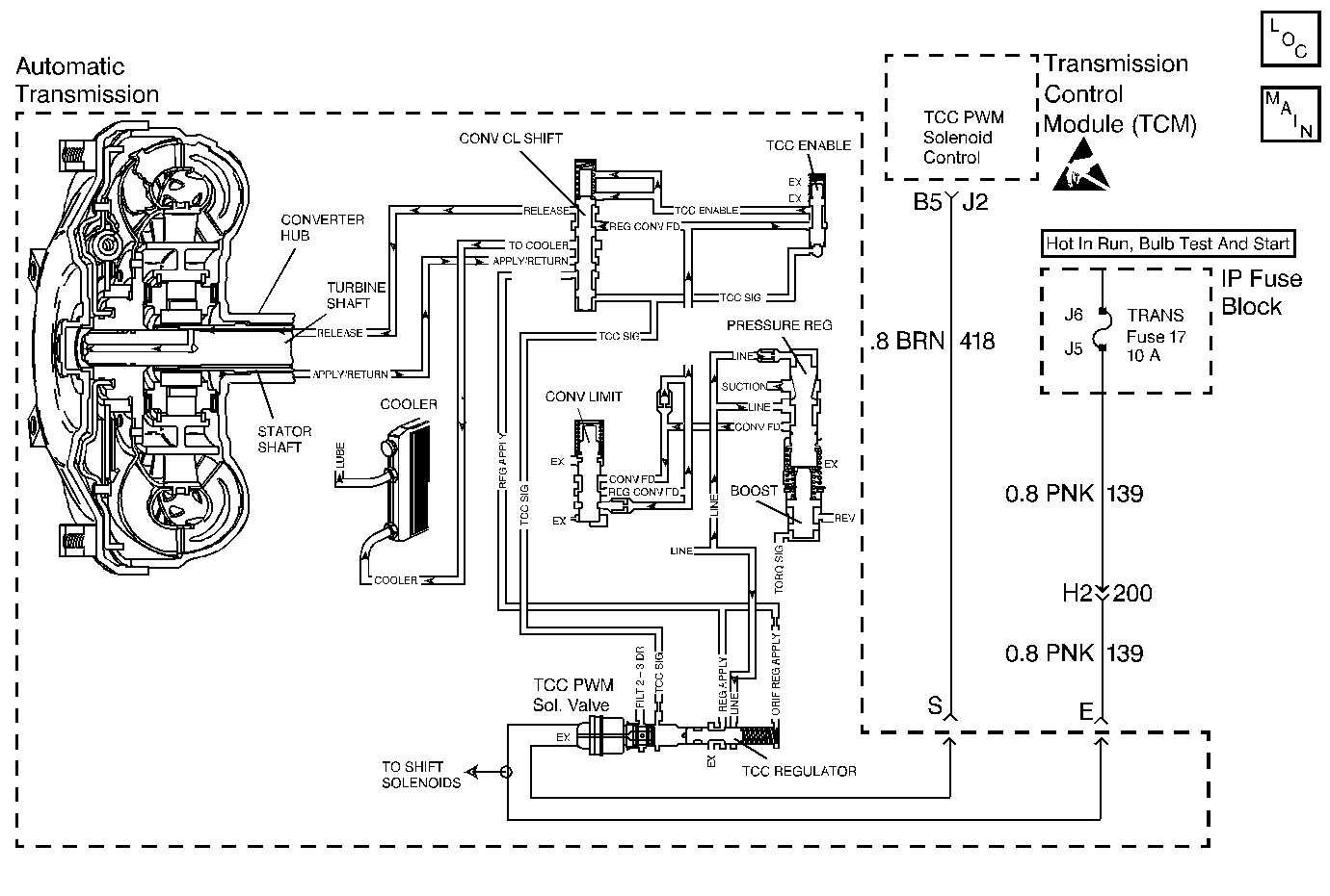
Circuit Description
Important: DTC 39 inspects for high Torque Converter Clutch (TCC) slip in 2nd and 3rd gear only. The transmission must be in hot mode or experiencing a wide open throttle maneuver in order for the TCC to be commanded ON in 2nd and 3rd gear.
The Transmission Control Module (TCM) energizes the Torque Converter Clutch Pulse Width Modulation Solenoid Valve (TCC PWM Sol. Valve) by grounding circuit 418. This blocks the exhaust for TCC signal fluid and allows filtered 23 drive fluid to feed the TCC signal circuit. When the vehicle's operating conditions are appropriate for TCC application, the TCM begins the TCC duty cycle to approximately 30%. This allows TCC signal fluid pressure to move the converter clutch shift valve into the apply position and direct regulated apply fluid to the torque converter. The TCM then increases (ramps) the duty cycle to approximately 60%, where regulated apply fluid pressure applies the converter clutch. The vehicle application determines the TCC apply rate. Once the TCC applies, the duty cycle immediately increases to approximately 70%, to achieve full apply pressure in the regulated apply fluid circuit. The TCC PWM Sol. Valve is de-energized by the TCM opening circuit 418. This action allows the TCC signal fluid to exhaust through the solenoid and blocks filtered 23 drive fluid from entering the TCC signal circuit. The loss of fluid pressure in the TCC signal circuit releases the TCC.
If the TCM detects high TCC slip when the TCC is commanded ON, then DTC 39 sets.
Conditions for Setting the DTC
| • | No TFP Val. Position Sw. DTC 28. |
| • | No camshaft position sensor circuit DTC 71. |
| • | No A/T ISS Sensor DTC 74. |
| • | The gear ratio must indicate 2nd or 3rd. |
| • | The TFP Val. Position Sw. must be in D4 or D3. |
| • | TCC duty cycle greater than 70%. |
| • | The TCC Slip Speed is greater than 65 RPM. |
| • | All conditions must be met for 2 seconds. |
Action Taken When the DTC Sets
| • | The TCM does not illuminate the Malfunction Indicator Lamp (MIL). |
| • | The TCM inhibits 4th gear if in hot mode. |
| • | DTC 39 is stored in TCM history. |
Conditions for Clearing the DTC
| • | The TCM clears the DTC from Current to History when the fault condition(s) no longer exist and the ignition switch is cycled OFF and then ON. |
| • | A scan tool can clear the DTC from Current and History status. The TCM clears the DTC from the TCM history if the vehicle completes 40 ignition cycles without a failure reported. |
| • | The TCM cancels the DTC default actions when the fault no longer exists and the ignition is cycled OFF and then ON. |
Diagnostic Aids
| • | Residue or contamination may cause shift valves to stick intermittently. |
| • | First diagnose and clear any TP Sensor codes that are present. Then inspect for any transmission DTCs that may have reset. |
Test Description
The numbers below refer to the step numbers on the diagnostic table.
-
This step tests for excessive TCC slip when TCC is commanded on.
-
This step inspects for possible causes of no TCC apply.
Step | Action | Value(s) | Yes | No | ||||
|---|---|---|---|---|---|---|---|---|
1 | Was the Powertrain On-Board Diagnostic (OBD) System Check performed? | -- | ||||||
Important:: Before clearing the DTC's, record the Current and History DTC's information for reference. The Clear Info function erases the stored Current and History DTC from the TCM. Is the TCC slip speed snapshot data greater than the specified value when the TCC Duty Cycle is commanded greater than 70% for greater than 3 seconds? | 140 RPM | Go to Diagnostic Aids | ||||||
Inspect the TCC PWM Sol. Valve for being mechanically stuck OFF. Refer to Torque Converter Clutch Diagnosis . Did you find the condition? | -- | |||||||
4 |
Did you find and correct the condition? | -- | -- | |||||
5 | In order to verify your repair, perform the following procedure:
Does the Scan Tool display a TCC slip of less than 20 RPM for 2 seconds? | -- | System OK | Begin the Diagnosis again |
