For 1990-2009 cars only
Removal Procedure
- Raise the front of the vehicle until the front wheel is off the floor. Support the vehicle with suitable safety stands.
- Remove the front hub/rotor from the spindle. Refer to Wheel Hub, Rotor, Bearing, and Seal Replacement .
- Remove the tie rod from the left and the right side knuckle.
- Remove the steering link rod from the right side knuckle only. Refer to Tie Rod Replacement in Steering Linkage.
- Remove the screws, the dust caps, and the O-rings from the knuckle.
- Remove the nut, the lock washer, and the tapered pin.
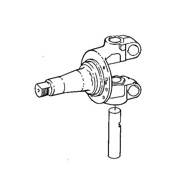
- Remove the king pin.
- Remove the knuckle, the shims and the thrust bearing from the axle center. Note the number of shims used for reassembly.
- Remove the lubrication fittings from the knuckle.
- Remove the knuckle bushing seals from the knuckle.
- Remove the knuckle bushings.
- Remove the inner wheel bearing cone from the spindle if replacing the knuckle. Refer to Wheel Hub, Rotor, Bearing, and Seal Replacement .
- Remove the cotter pin, the castellated nut, the steering arm, and the steering arm key from the knuckle yoke.
- Remove the steering knuckle stop screw and the jam nut from the knuckle.
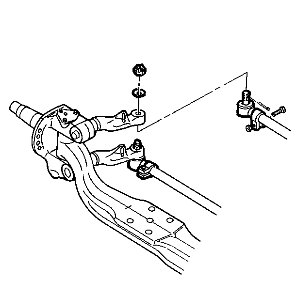
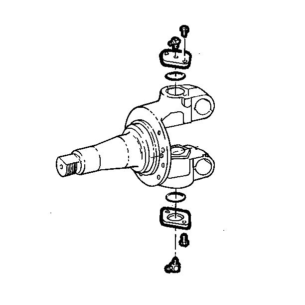
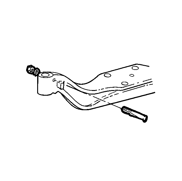
Drive the tapered pin from the knuckle with a bronze drift on the threaded end.
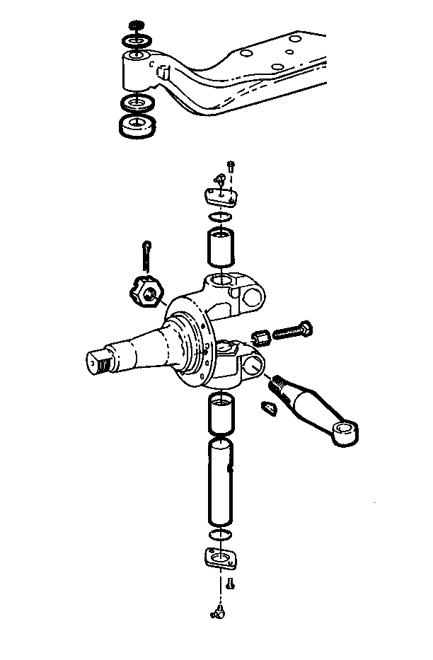
Drive the king pin out of the knuckle with a drift.
Use the bushing removing and installing tool to drive out the bushings.
Cleaning Procedure
- Clean all traces of lubricant from the steering knuckle and the spindle.
- Clean dirt and lubricant from the king pin.
- Clean all traces of lubricant from the axle center.
Inspection Procedure
- Inspect the knuckle and the spindle for signs of excessive wear, bending, cracking, pitting or metal fatigue.
- Inspect the king pins for signs of chipping, pitting or wear.
- Inspect the bearing cones and cups for wear or pitting.

Installation Procedure
- Install the knuckle bushings in the knuckle.
- Align the lubricating holes on the bushing with the holes in the knuckle. Press bushings into the holes in the knuckle.
- Use the removing/installing tool in order to press bushings.
- Ream the new bushings. Refer to Reaming Knuckle Bushings .
- Install the seals in the recesses in the knuckle below the top and above the bottom bushing.
- Install the lubrication fittings in the knuckle.
- Position the steering knuckle on the axle center.
- Install the thrust bearing between the lower face of the axle center and the lower knuckle yoke.
- Align the holes in the knuckle yokes, the thrust bearing and the axle center.
- Place a floor or bottle jack under the knuckle yoke and raise the knuckle in order to remove all clearance between the lower yoke, the thrust bearing and the axle center.
- Check the clearance between the top face of the axle center and the face of the knuckle yoke with a feeler gauge. Clearance must be between 0.051-0.254 mm (0.002-0.010 in). Install shims until the clearance is within this range.
- Install the king pin into the steering knuckle and the axle center.
- Remove the jack from under the knuckle yoke.
- Install the tapered pin into the axle center with the flat side positioned to mate with the flat on the king pin. Fasten the pin securely with a lock washer and a nut.
- Install the O-rings and the dust caps on the knuckle with screws.
- Install the steering knuckle stop screw and the jam nut in the knuckle, if removed.
- Install the inner wheel bearing cone on the spindle, if removed.
- Install the steering arm, the castellated nut, and the cotter pin on the knuckle yoke, if removed.
- Install the tie rod on the left and right side knuckle.
- Install the steering link rod on the right side knuckle only. Refer to Tie Rod Replacement in Steering Linkage.
- Install the front hub/rotor assembly. Refer to Wheel Hub, Rotor, Bearing, and Seal Replacement .
- Lubricate all the steering fittings.
- Remove the safety stands.
- Check the front end alignment and adjust it if necessary. Refer to Wheel Alignment Specifications in Wheel Alignment.
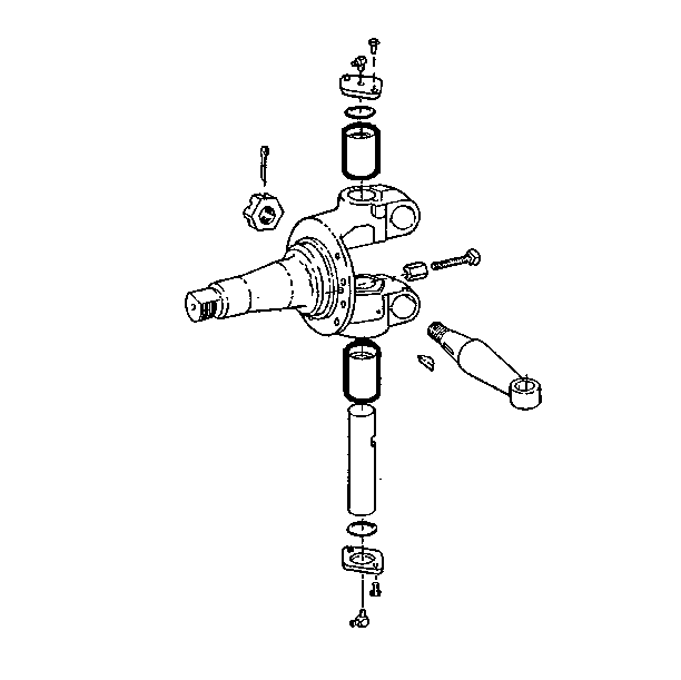
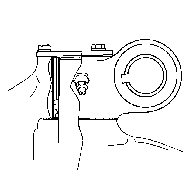

Align the flat on the king pin to mate with the tapered hole in the axle center. Insert the king pin from the top of the knuckle and hand push or drive it into position.


