Vectoring is a technique that reduces radial or lateral
runout and evens dynamic balance on tire and wheel assemblies. You accomplish
vectoring by positioning the tire on the wheel and then by positioning the
tire and wheel assembly on the hub/rotor.
Important: Always rebalance the tire and wheel assembly after you vector.
Tire to Wheel Vectoring
Perform the following vectoring procedure:
- Determine visually which runout needs to be minimized.

- If radial runout is the problem, take a
measurement on the center tread rib.
- If the tread is uneven, wrap tape tightly around the tire. Record
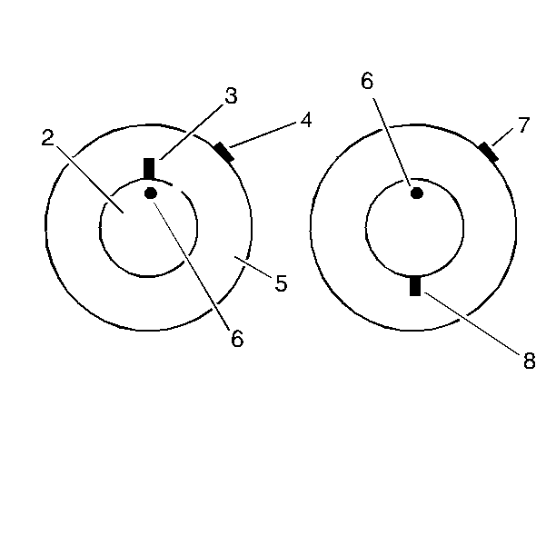
the runout magnitude. Mark the high spot location (4).
- If lateral runout is the problem, take a measurement on the tire
side wall just below the edge of the tread shoulder (5). Record the runout
magnitude. Mark the high spot location.
- Mark the tire side wall (3) at the valve location (6).
| 5.1. | This is the 12 O'clock position. |
| 5.2. | The high spot always relates to the clock position on the wheel. |

- Break down the tire and wheel
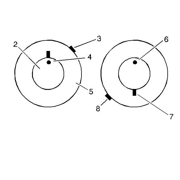
assembly on a tire mounting machine. Rotate the tire 6 hours (180 degrees)
on the rim.
| 6.1. | Reinflate the tire. Measure the runout in question. |
| 6.2. | Record the magnitude. Record the location of the high spot (3)
(The valve stem is at the 12 O'clock position)(4). |
- If the clock location of the high spot remains at or near the
clock location of the original high spot, then the rim is causing the runout
problem.
| 7.1. | Confirm this by removing the tire from the wheel. Check the wheel
rim runout. |
| 7.2. | If the wheel rim runout exceeds specifications, replace the wheel. |
- If the clock position of the high spot is 6 hours from
the original high spot, then the tire is causing the runout problem. Replace
the tire.
- After correcting the tire to the wheel vectoring, rebalance the
tire and wheel assembly. Refert to Tire and Wheel Balancing
.
Tire and Wheel Assembly to Hub/Rotor Vectoring
Perform the following vectoring procedure:

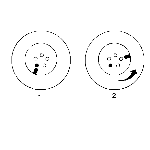
- Mark the wheel bolt nearest the valve stem for reference.
- Rotate the tire and wheel assembly 2 wheel bolts. Recheck the
runout.
| • | Try several positions in order to locate the optimum location. |
| • | This is effective for both radial and lateral runout. |
- If there is looseness in the wheel bolt holes, reduce radial runout
by slightly loosening the wheel bolt nuts. Move the wheel position on the
bolts. Then retighten the nuts.
- Balance the tire and the wheel to the hub/rotor assembly. This
compensates for any imbalance in the brake rotor, the drum, or the wheel cover.


