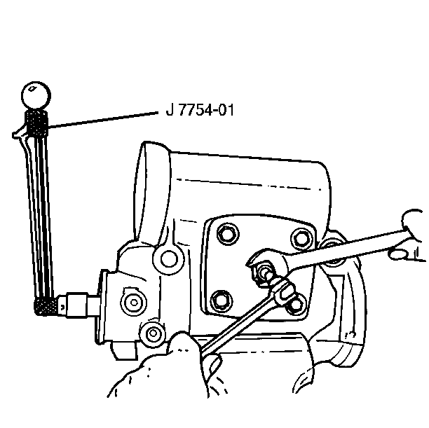
Adjustment Procedure
- Check the worm bearing preload adjustment. Adjust the worm bearing if necessary.
- Turn the over-center adjusting screw all the way out clockwise and then turn it in one-half turn.
- Place the torque wrench with a ¾ inch twelve-point socket on the stub shaft.
- Rotate the stub shaft from one stop to the other. Count the turns. Turn the stub shaft back to the center.
- Check the over-center preload by rotating the torque wrench through a 180 degree arc on each side of the center. Record the highest readings. Readings must be 0.8-1.9 N·m (7-17 lb in).
- Turn the over-center adjusting screw counterclockwise until the torque wrench shows a reading of 0.7-1.1 N·m (6-10 lb in) higher than the reading you recorded in the previous step. The total reading must not exceed 3 N·m (27 lb in).
- Check the adjustment and adjust again if necessary.
- Connect the hydraulic hoses following the tag locations.
- Connect the cardan clamp.
- Install the cardan clamp bolt. Adjust the cardan clamp bolt.
- Connect the pitman arm. Refer to Pitman Arm Replacement in Steering Linkage.

Tighten
Hold the adjustment screw while you tighten the adjustment lock nut
to 89 N·m (66 lb ft).
Notice: Use the correct fastener in the correct location. Replacement fasteners must be the correct part number for that application. Fasteners requiring replacement or fasteners requiring the use of thread locking compound or sealant are identified in the service procedure. Do not use paints, lubricants, or corrosion inhibitors on fasteners or fastener joint surfaces unless specified. These coatings affect fastener torque and joint clamping force and may damage the fastener. Use the correct tightening sequence and specifications when installing fasteners in order to avoid damage to parts and systems.
Tighten
Tighten the high pressure connections to 38 N·m (28 lb ft)
