NOTICE: Ensure that all fasteners are securely seated before tightening to the
specified torque value. Failure to do so may result in component damage or
steering column malfunction.

- Move the lock
cylinder set to the OFF/LOCK position.
Important: The solenoid will get hot during adjustment and inspection procedures.
- Adjust the ignition switch assembly.
| 2.1. | Move the switch slider to the extreme right position. |
| 2.2. | Move the switch slider one detent to the left of the OFF/LOCK
position. |
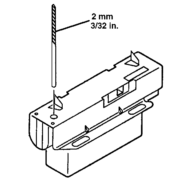
| 2.3. | Install a 3/32 inch drill bit in the hole on the switch
in order to limit travel. |
NOTICE: Install the ignition switch to the cable and actuator assembly with
the switch in the OFF/LOCK position. The new ignition switch will be pinned
in the OFF/LOCK position. Remove the plastic pin after the switch is assembled
to the column. Failure to do so may cause switch damage.

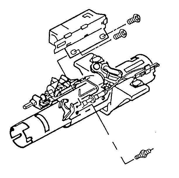
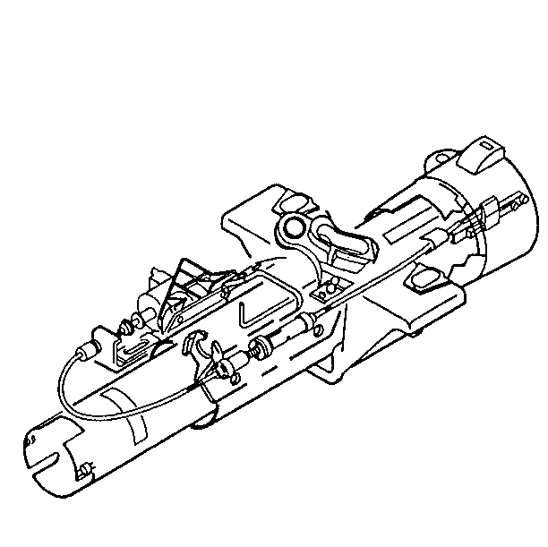
- Install the
ignition switch assembly.
- Install the two washer head screws.
Tighten
Tighten the washer head screws to 4 N·m (35 lb in).
Notice: Use the correct fastener in the correct location. Replacement fasteners
must be the correct part number for that application. Fasteners requiring
replacement or fasteners requiring the use of thread locking compound or sealant
are identified in the service procedure. Do not use paints, lubricants, or
corrosion inhibitors on fasteners or fastener joint surfaces unless specified.
These coatings affect fastener torque and joint clamping force and may damage
the fastener. Use the correct tightening sequence and specifications when
installing fasteners in order to avoid damage to parts and systems.
- Remove the drill bit from the ignition switch.
- Install the dimmer switch. Refer to Dimmer Switch.
- Connect the vehicle wire harness connector to the ignition switch.

- Check the interlock solenoid assembly
for proper function.
| 8.1. | The solenoid must lock the gearshift lever bowl assembly whenever
the steering column in the P (Park) and when trying to shift from P (Park)
without pressing the brake pedal (the solenoid is energized). |
| 8.2. | The solenoid must release the gearshift lever bowl assembly when
pressure is applied to the brake pedal (the solenoid is de-energized). |
| 8.3. | Make any necessary adjustments. |


