Steering Column Replacement P72
Removal Procedure
- Set the front wheels in the straight-ahead position and the steering wheel in the LOCKED position.
- Mark the relationship of the steering coupling shaft to the steering shaft.
- Disconnect the negative battery cable. Refer to
Caution: Unless directed otherwise, the ignition and start switch must be in the OFF or LOCK position, and all electrical loads must be OFF before servicing any electrical component. Disconnect the negative battery cable to prevent an electrical spark should a tool or equipment come in contact with an exposed electrical terminal. Failure to follow these precautions may result in personal injury and/or damage to the vehicle or its components.
in General Information. - Remove the transmission control linkage from the column shift tube levers. Refer to Transmission Control Cable in Transmission.
- Remove the upper cardan joint pinchbolt and the nut. Refer to Steering Coupling Shaft Replacement.
- Disconnect the steering column wiring harness at the connectors.
- Disconnect the park/neutral position switch and the backup light switch connectors. Refer to Backup Light Switch in Lighting Systems.
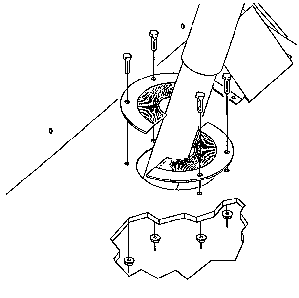
- Remove the bolts, the nuts, and the steering column seal from the floor.
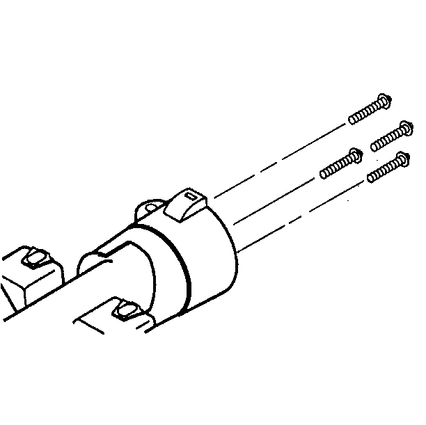
- Remove the screws and the shield from the upper steering column support assembly.
- Remove the bolts and the upper steering column support assembly from the brake pedal bracket assembly.
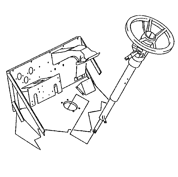
- Remove the steering column assembly. Rotate the column so that the shift lever clears the floor opening.
Important:: A sharp blow to the end of the steering shaft or shift lever, leaning on the column assembly, or dropping the assembly could shear or loosen the plastic fasteners that maintain column rigidity when the column is removed from the vehicle.
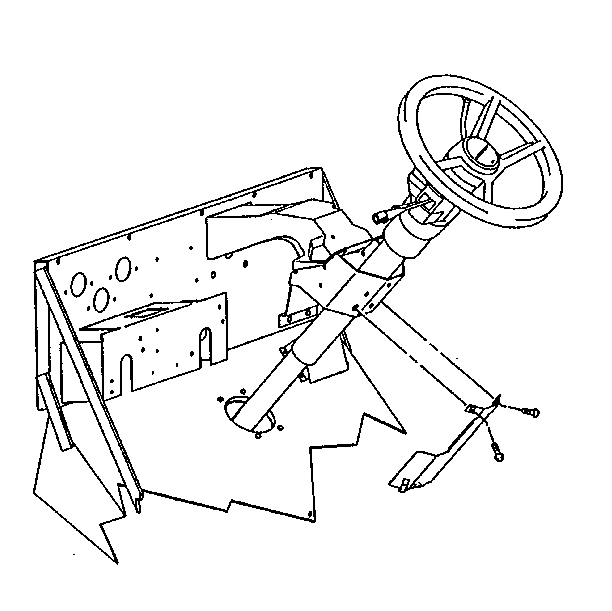
Important:: Refer to the coach manufacturer's service manual for instructions on removing the trim around the upper steering column support.
Installation Procedure
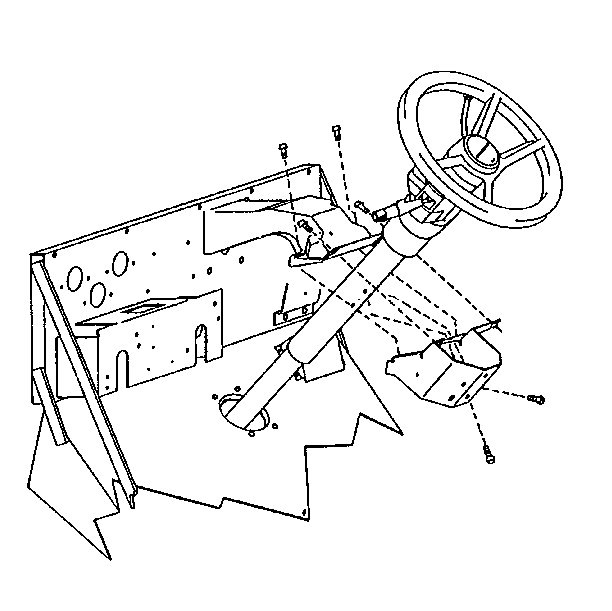
- Install the steering column. Rotate the column so that the shift lever clears the floor opening.
- Position the steering column against the brake pedal bracket assembly.
- Use the bolts to install the upper steering column support assembly to the brake pedal bracket assembly.
- Use the screws to install the shield to the steering column.
- Use the bolts and the nuts to install the seal around the steering column on the floor.
- Connect the steering column wiring harness at the connectors.
- Connect the park/neutral position and backup light switch. Refer to Backup Light Switch in Lighting Systems.
- Install the upper cardan joint pinch bolt and the nut. Refer to Steering Coupling Shaft Replacement.
- Install the transmission control linkage to the column shift tube levers. Refer to Transmission Control Cable in Transmission.
- Connect the negative battery cable.


Tighten
Tighten the screws to 20-30 N·m (15-22 lb ft).
Notice: Use the correct fastener in the correct location. Replacement fasteners must be the correct part number for that application. Fasteners requiring replacement or fasteners requiring the use of thread locking compound or sealant are identified in the service procedure. Do not use paints, lubricants, or corrosion inhibitors on fasteners or fastener joint surfaces unless specified. These coatings affect fastener torque and joint clamping force and may damage the fastener. Use the correct tightening sequence and specifications when installing fasteners in order to avoid damage to parts and systems.
Important:: Refer to the coach manufacturer's service manual for instructions on installing the trim around the upper steering column support.

Tighten
Tighten the bolts to 25 N·m (18 lb ft).
Steering Column Replacement P92
Removal Procedure
- Set the front wheels in the straight-ahead position.
- Mark the relationship of the steering coupling shaft to the steering shaft.
- Disconnect the negative battery cable. Refer to
Caution: Unless directed otherwise, the ignition and start switch must be in the OFF or LOCK position, and all electrical loads must be OFF before servicing any electrical component. Disconnect the negative battery cable to prevent an electrical spark should a tool or equipment come in contact with an exposed electrical terminal. Failure to follow these precautions may result in personal injury and/or damage to the vehicle or its components.
in General Information. - Remove the steering wheel. Refer to Steering Wheel Replacement.
- Remove the upper cardan joint pinch bolt and the nut. Refer to Steering Coupling Shaft Replacement.
- Disconnect the steering column wiring harness at the connectors.
- Remove the bolts and the steering column assembly from the steering column support.
Important: The P92 chassis is shipped to the coach manufacturer without the steering column or the steering coupling shaft installed. Therefore, the following steps may not apply to every P92 chassis. Refer to the coach manufacturer's service manual for information on the removal and the installation of the P92 steering column.
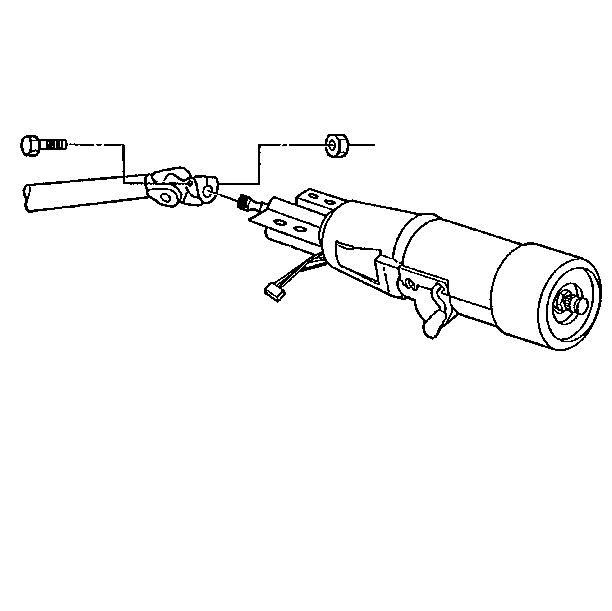
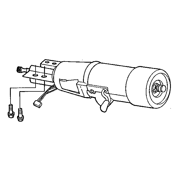
Installation Procedure
- Use the bolts to install the steering column assembly to the steering column support.
- Connect the steering column wiring harness at the connectors.
- Install the upper cardan joint pinch bolt and the nut. Refer to Steering Coupling Shaft Replacement.
- Install the steering wheel. Refer to Steering Wheel Replacement.
- Connect the negative battery cable.
- Inspect the steering column to ensure that there are no wires, air lines, or hydraulic lines lying on the rotating components. The rotating motion of the shaft will wear through anything lying against it. This will cause problems as the vehicle accumulates miles.
- Rotate the steering wheel to the extreme right position and to the extreme left position. There should be no roughness or catching as the steering wheel is rotated. If there is, inspect the entire steering system and make the necessary adjustments or repairs.


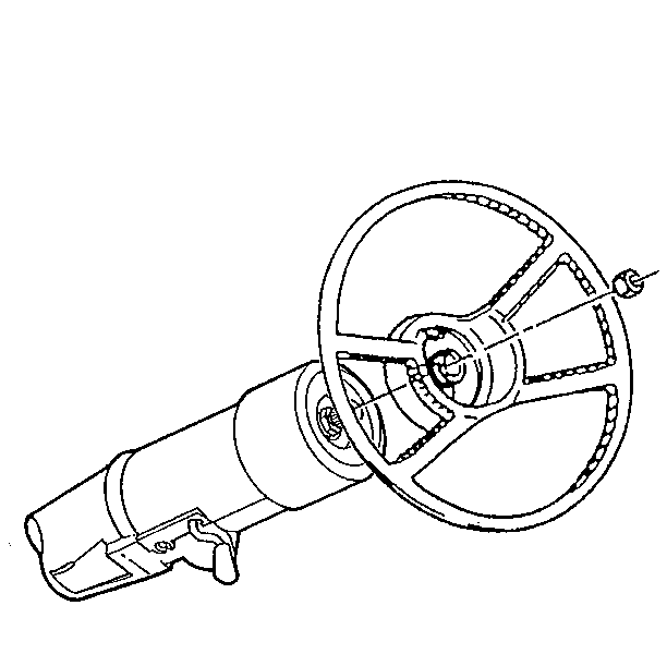
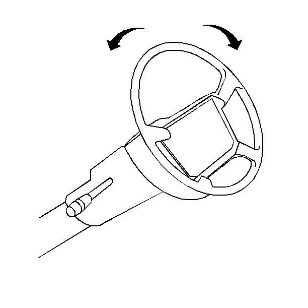
Steering Column Replacement Upper Column-Column Shift
Removal Procedure
Tools Required
J 23653-D Lock Plate Compressor
- Remove the steering wheel before doing the following procedure. Refer to Steering Wheel Replacement.
- Disconnect the negative battery cable. Refer to
Caution: Unless directed otherwise, the ignition and start switch must be in the OFF or LOCK position, and all electrical loads must be OFF before servicing any electrical component. Disconnect the negative battery cable to prevent an electrical spark should a tool or equipment come in contact with an exposed electrical terminal. Failure to follow these precautions may result in personal injury and/or damage to the vehicle or its components.
in General Information. - Remove the connector body bracket.
- Remove the wiring protector.
- Remove the shaft lock retaining ring using J 23653-D to push down the shaft lock.
- Discard the shaft lock retaining ring.
- Remove the shaft lock.
- Remove the turn signal cancel cam.
- Remove the upper bearing spring.
- Remove the upper bearing inner race seat.
- Remove the race.
- Shift the turn signal lever to the RIGHT TURN position.
- Remove the multifunction lever. Refer to Multifunction Turn Signal Lever.
- Disconnect the hazard warning button. Refer to Hazard Warning Knob.
- Remove the round washer head screw and the signal switch arm.
- Remove the binding head cross-recess screws.
- Disconnect the turn signal switch assembly.
- Remove the switch.
- Remove the two round washer head screws.
- Remove the transmission indicator dial and the housing assembly.
- Remove the transmission indicator pointer.
- Remove the hexagon washer head screw.
- Remove the socket and bracket assembly from the bracket and cover assembly.
- Follow these steps to remove the socket and bracket assembly:
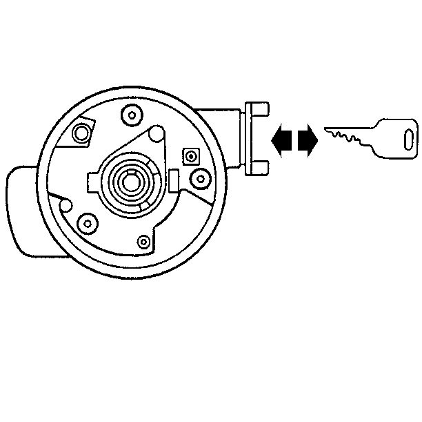
- Remove the key from the steering column lock cylinder set.
- Disconnect the buzzer switch assembly.
- Reinsert the key in the lock cylinder set. Place the key in the LOCK position.
- Remove the lock retaining screw.
- Remove the lock cylinder set.
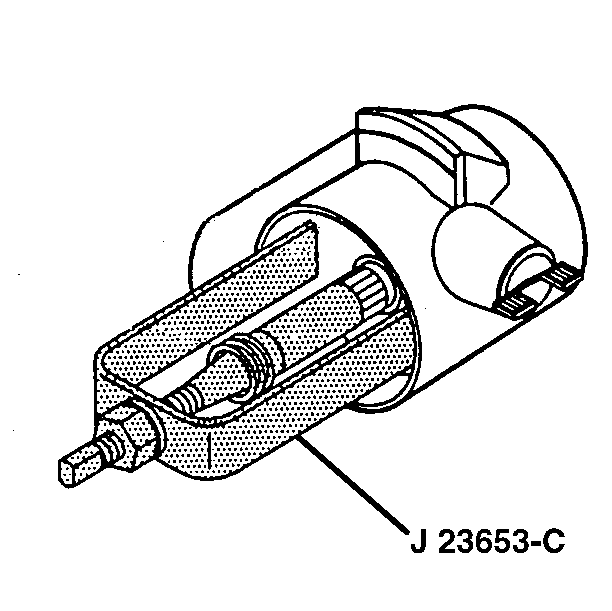
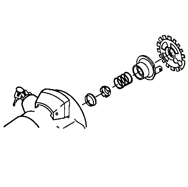

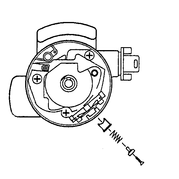
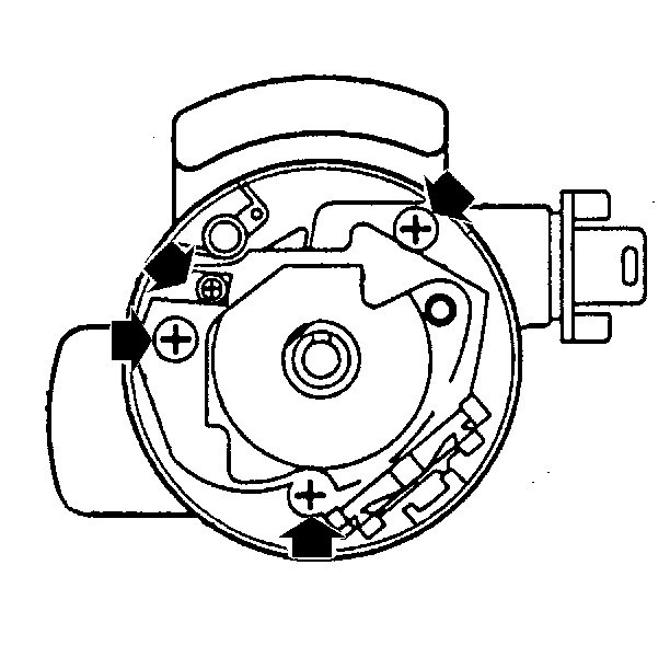
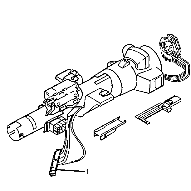
Let the switch hang freely, if removal is unnecessary.
| 18.1. | Disconnect the turn signal switch connector from the connector body bracket and the vehicle wiring harness. |
| 18.2. | Disconnect the socket and bracket assembly connector terminal from slot 1 of the turn signal switch connector. |
| 18.3. | Remove the connector body bracket. |
| 18.4. | Remove the wiring protector. |
| 18.5. | Gently pull the wire harness through the column. |
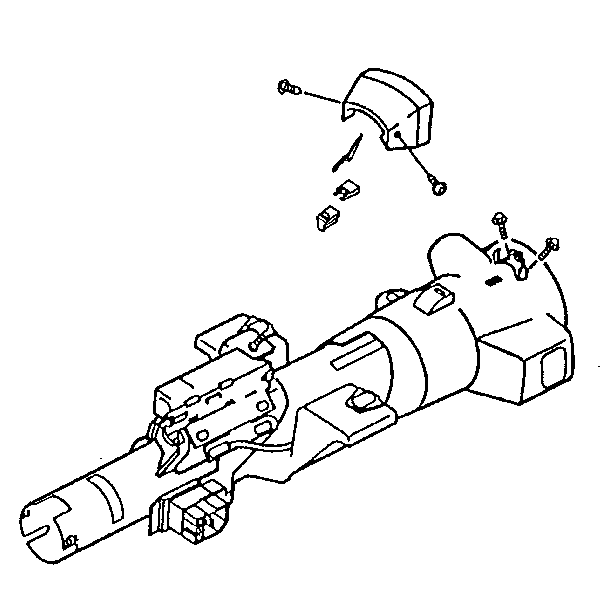
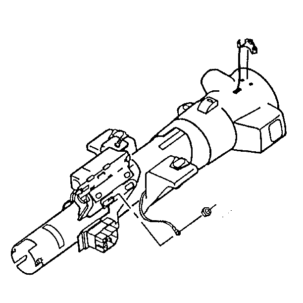
| 24.1. | Remove the hexagon nut from the dimmer switch mounting stud. |
| 24.2. | Remove the ground terminal ring. |
| 24.3. | Attach a length of mechanic's wire to both the terminals to aid in reassembly. |
| 24.4. | Gently pull the wire harness through the column. |
| 24.5. | Remove the bracket assembly and the wire harness from the cover assembly. |
Installation Procedure
Tools Required
J 23653-D Lock Plate Compressor
- Install the socket and bracket assembly wiring harness through the bracket and cover assembly and the steering column.
- Install the ground ring terminal and the hexagon nut to the dimmer switch mounting stud.
- Install the bracket assembly to the cover assembly using the hexagon head screw.
- Install the transmission indicator pointer.
- Install the transmission indicator dial and the housing assembly using the two round washer head screws.
- Adjust the shift lever to the N (Neutral) position.
- Move the indicator pointer into the N (Neutral) position on the transmission indicator dial.
- Install the pointer retaining clip. Make sure the bracket teeth are seated in the bowl assembly grooves.
- Install the steering column lock cylinder set.
- Install the lock retaining screw.
- Insert the key from the lock cylinder set.
- Connect the buzzer switch assembly.
- Reinsert the key in the lock cylinder set. Place the key in the LOCK position.
- Insert the turn signal switch assembly wire harness through the steering column. Allow the switch to hang freely.
- Connect the socket and bracket assembly connector terminal to slot 1 of the switch connector.
- Use the screws to install the turn signal switch assembly.
- Connect the hazard warning button knob assembly. Refer to Hazard Warning Knob.
- Use the round washer head screw to install the signal switch arm.
- Install the multifunction lever. Refer to Multifunction Turn Signal Lever.
- Install the inner race.
- Install the upper bearing inner race seat.
- Install the bearing spring.
- Install the turn signal cancel cam.
- Lubricate the cancel cam with synthetic grease.
- Install the shaft lock.
- Install the new shaft lock retaining ring using J 23653-D to push down the shaft lock.
- Install the wiring protector.
- Attach the connector body bracket.
- Install the steering wheel. Refer to Steering Wheel Replacement.
- Connect the negative battery cable.
NOTICE: Ensure that all fasteners are securely seated before tightening to the specified torque value. Failure to do so may result in component damage or steering column malfunction.
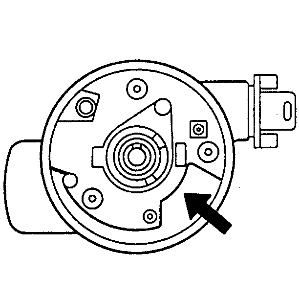
Slip the wiring down through the steering column at the 5 o'clock position.

Tighten
Tighten the hexagon nut to 4.0 N·m (35 lb in).
Notice: Use the correct fastener in the correct location. Replacement fasteners must be the correct part number for that application. Fasteners requiring replacement or fasteners requiring the use of thread locking compound or sealant are identified in the service procedure. Do not use paints, lubricants, or corrosion inhibitors on fasteners or fastener joint surfaces unless specified. These coatings affect fastener torque and joint clamping force and may damage the fastener. Use the correct tightening sequence and specifications when installing fasteners in order to avoid damage to parts and systems.
Tighten
Tighten the hexagon head screw to 2.3 N·m (20 lb in).

Tighten
Tighten the round washer head screws to 1.4 N·m (12 lb in).

Tighten
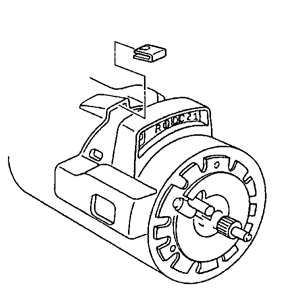
Tighten the lock retaining screw to 2.5 N·m (22 lb in).

Tighten
Tighten the screws to 3.4 N·m (30 lb in).

Tighten
Tighten the round washer head screw to 2.3 N·m (20 lb in).


Make sure the shaft lock retaining ring is firmly seated in the groove on the shaft.
NOTICE: Gently pull the turn signal wires in order to remove any wire kinks that may be hidden from sight inside the steering column assembly. Failure to remove kinks may result in damage to the wire harness.
Inspection Procedure
| • | Check the function of the turn signal switch. |
| • | Place the switch lever in the right turn position. Turn the wheel to the left. |
| The switch should cancel to the center position. |
| • | Place the switch lever in the left turn position. Turn the wheel to the right. |
| Again, the switch should cancel to the center position. |
| • | If the turn signal switch does not cancel to the center position, check the switch for the following: |
| • | A broken cancel spring |
| • | A missing cancel spring |
| • | A worn or damaged cancel cam. |
Steering Column Replacement Housing Cover-Column Shift
Removal Procedure
Tools Required
| • | J 23653-D Lock Plate Compressor |
| • | J 39246 Tilt Spring Compressor |
- Remove the steering wheel before doing the following procedure. Refer to Steering Wheel Replacement.
- Remove the tilt lever. Refer to Tilt Lever Replacement.
- Remove the column housing cover end cap.
- Disconnect the dimmer switch rod actuator.
- Take off the wire protector shield.
- Remove the switch actuator pivot.
- Remove the pivot and (pulse) switch assembly.
- To remove the switch, perform the following:
- Seat the counterbore of tool J 39246 over the end of the race and the upper shaft assembly.
- Thread and seat the standard hexagon nut on the shaft.
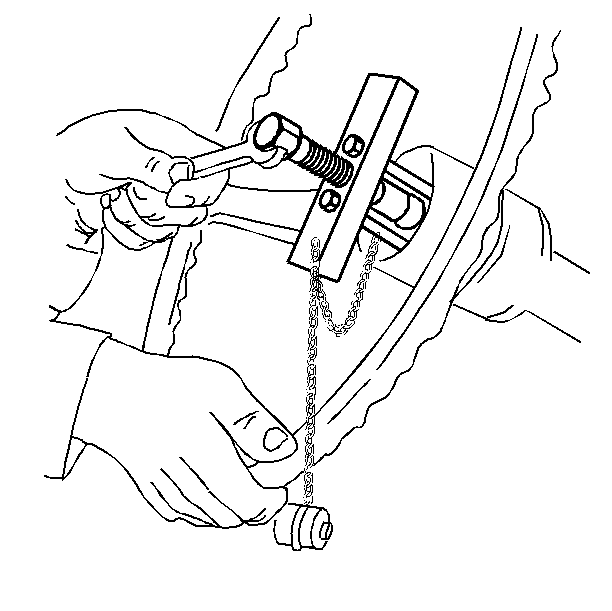
- Align the square extension on the end of the tool bolt with the square hole in the spring retainer and seat.
- Rotate the tool bolt clockwise with the wrench until it contacts the surface of the tool block.
- Seat the counterbore of the tool over the steering shaft and secure with a standard nut.
- To remove the spring retainer, turn the spring retainer clockwise.
- Inspect the spring retainer. The square hole in the spring retainer may become stripped. Ensure the spring retainer is compressed at least 6.35 mm (1/4 in) into the steering column and is turned no more than 1/4 turn.
- Rotate the hexagon section on the end of the tool bolt counterclockwise approximately 1/4 turn.
- Unscrew the tool bolt until the wheel tilt spring and the retainer are loose and free of the tool.
- Remove the following components.
Important: Remove only those components necessary to make repairs.
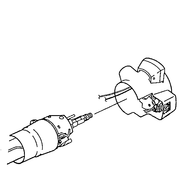
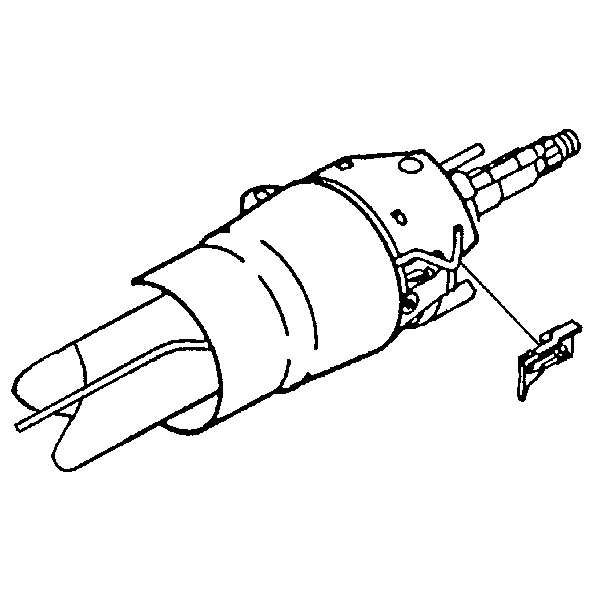
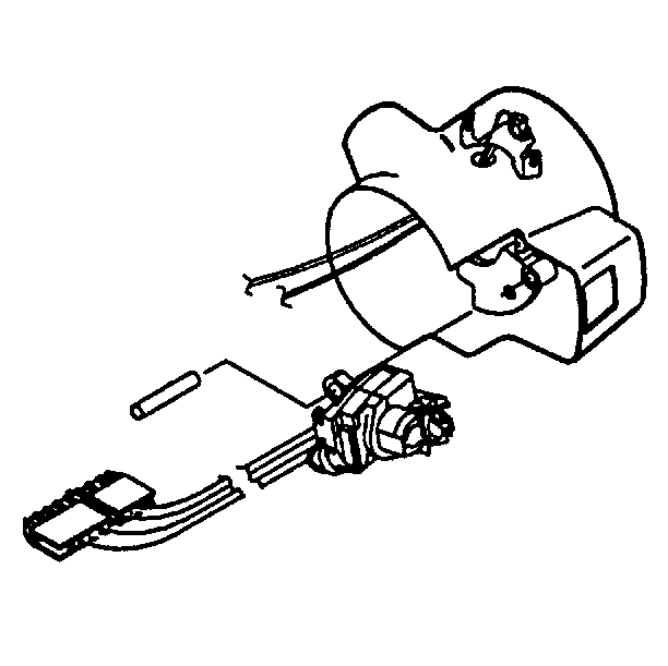
Let the switch hang freely if removal is not necessary.
| 8.1. | Remove the pivot and (pulse) switch connector from the vehicle wiring harness. |
| 8.2. | Gently pull the wire harness through the column. |
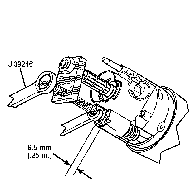
| • | The retainer and the retainer spring |
| • | The spring guide |
| • | Tool J 39246 . |
Installation Procedure
- Install the spring, the spring guide, and the spring retainer to the steering column housing.
- Align the securing tabs on the spring retainer with the slots in the column housing.
- Install tool J 23653-D to the steering shaft and the retainer.
- To set up the tool and compress the spring, perform the following steps:
- Rotate the hexagon section on the end of the tool bolt clockwise approximately 1/4 turn. This will lock the retainer into place.
- Unscrew the tool bolt and remove the tool bolt from the shaft.
- Move the tilt housing to all positions to ensure smooth and proper operation of the tilt spring.
- Set the tilt housing to the center position for standard columns.
- Install the pivot and (pulse) switch assembly to the bracket and cover assembly.
- Install the switch actuator pivot pin to the pivot and (pulse) switch and the cover.
- Insert the pivot and (pulse) switch wire harness through the steering column.
- Install the switch connector to the vehicle harness.
- Install the wire protector shield.
- Install the dimmer switch rod actuator to the column housing cover end cap.
- Lubricate the rod actuator with lithium grease.
- Install the cover end cap to the cover assembly.
- Install the multifunction lever and the tilt lever. Refer to Tilt Lever Replacement.
NOTICE: Ensure that all fasteners are securely seated before tightening to the specified torque value. Failure to do so may result in component damage or steering column malfunction.
Important: If a new wheel tilt spring is to be installed, grease the spring and the spring guide.

| 4.1. | Seat the counterbore of tool J 39246 over the end of the race and the upper shaft assembly. |
| 4.2. | Thread and seat the standard hexagon nut on the shaft. |
| 4.3. | Align the square extension on the end of the tool bolt with the square hole in the spring retainer and seat. |
| 4.4. | Rotate the tool bolt clockwise with the wrench until it contacts the surface of the tool block. |
| 4.5. | Seat the counterbore of the tool over the steering shaft and secure with a standard nut. |
| 4.6. | To remove the spring retainer, turn the spring retainer clockwise. |
| 4.7. | Inspect the spring retainer. The square hole in the spring retainer may become stripped. Ensure the spring retainer is compressed at least 6.35 mm (1/4 in) into the steering column and is turned no more than 1/4 turn. |
The spring and the retainer must be locked into position in the housing.


The bottom edge of the dimmer switch rod actuator must rest on the bend in the dimmer switch rod.
Steering Column Replacement Mid Column-Column Shift
Removal Procedure
Tools Required
| • | J 23653-D Plate Compressor |
| • | J 21854-01 Pivot Pin Remover |
| • | J 22635 Lock Shoe and Release Lever Pin Remover and Installer |
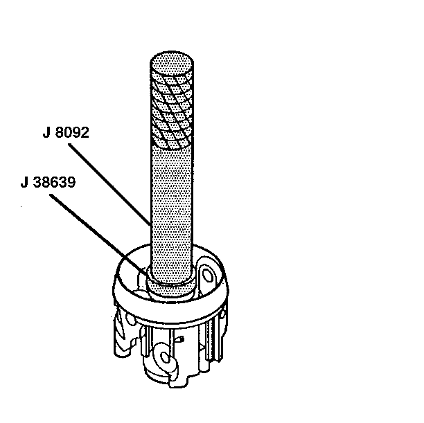
| • | J 8092 Driver Handle |
| • | J 38639 Steering Column Housing Bearing Installer |
| • | J 23073-01 Shift Tube Installer |
| • | J 39246 Tilt Spring Compressor |
- Remove the steering wheel before doing the following procedure. Refer to Steering Wheel Replacement.
- Disconnect the negative battery cable. Refer to
Caution: Unless directed otherwise, the ignition and start switch must be in the OFF or LOCK position, and all electrical loads must be OFF before servicing any electrical component. Disconnect the negative battery cable to prevent an electrical spark should a tool or equipment come in contact with an exposed electrical terminal. Failure to follow these precautions may result in personal injury and/or damage to the vehicle or its components.
in General Information. - Remove the steering column from the vehicle. Refer to Steering Column Replacement.
- Remove the pivot pins using J 21854-01 .
- Remove the steering column housing assembly. To do this, pull back on the tilt lever and pull the steering column housing assembly down and away from the column.
- Disassemble the steering column housing assembly. Refer to Steering Column Housing Assembly.
- Remove the bearing and the seal retainer.
- Remove the lower spring retainer. Discard the retainer.
- Remove the lower bearing spring.
- Remove the lower bearing seat.
- Remove the two hexagon washer head screws.
- Remove the adapter and the bearing assembly.
- Remove the inner race seat.
- Remove the steering shaft assembly and the steering shaft collapse clip.
- Inspect the steering shaft assembly for accident damage. Refer to Inspection Required After an Accident.
- Remove the support screws and discard the screws.
- Remove the steering column housing support assembly and the dimmer switch rod from the steering column jacket assembly.
- Remove the oval head cross-recess screws and the shift lever gate from the support.
- Remove the shift tube retaining ring.
- Remove the two thrust washers.
- Remove the lock plate.
- Remove the wave washer.
- Remove the two thrust washers.
- Remove the cam retainer and the cable shift cam assembly.
- Remove the gearshift lever bowl assembly, the gearshift bowl shroud and the shift tube assembly.
- Remove the shift lever spring from the bowl.
- Remove the shroud from the bowl.
- Use a press to remove the shift tube from the bowl.
- Remove the Torx washer head screw and the nut from the dimmer switch assembly.
- Remove the dimmer switch from the dimmer switch mounting stud.
- Remove the two washer head screws from the ignition switch assembly.
- Remove the ignition switch from the cable and actuator assembly.
- Remove the dimmer switch mounting stud.
- Remove the cable and actuator assembly from the steering column jacket assembly and the interlock solenoid assembly.
- Remove the hexagon washer head screw.
- Remove the interlock solenoid assembly from the solenoid bracket.
- Remove the two lever support mounting screws.
- Remove the deflector plate and the solenoid bracket.
Important: Remove only those components necessary to make any repairs.
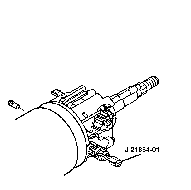
NOTICE: Once the steering column has been removed from the vehicle, it is extremely susceptible to damage. Dropping the steering column on its end could collapse the steering shaft or loosen the plastic injections which maintain column rigidity. Leaning on the steering column assembly could cause the jacket to bend or deform. Any of the above damage could impair the column's collapsible design. Use only the specified steering wheel puller to remove the steering wheel. Under no conditions should the end of the shaft be hammered on as hammering could loosen the plastic injections which maintain column rigidity.
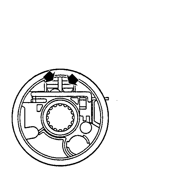
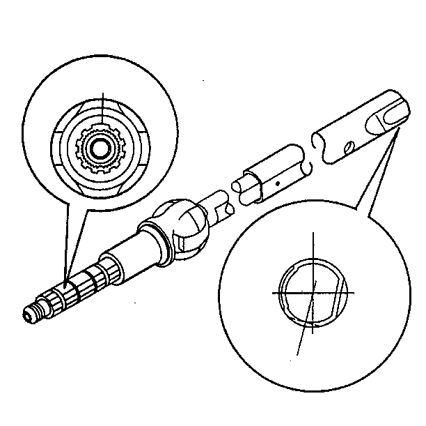
Important: To ensure proper assembly, mark the race and upper shaft assembly and the lower steering shaft assembly. Improper assembly will cause the steering wheel to be turned 180 degrees. Upon assembly, ensure that the notch bolt (on the upper shaft) is at the 7 o'clock position relative to the block tooth (on the lower shaft).
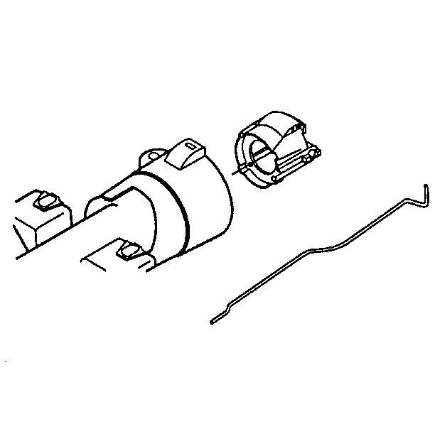
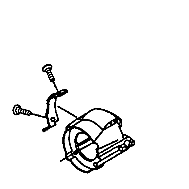
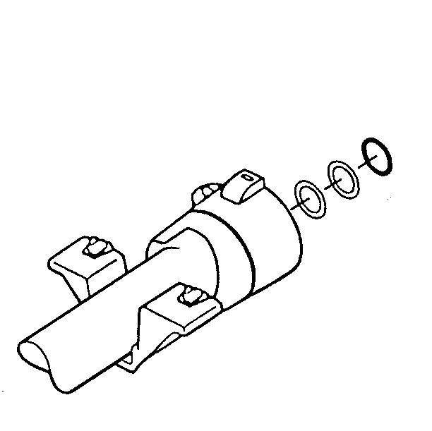
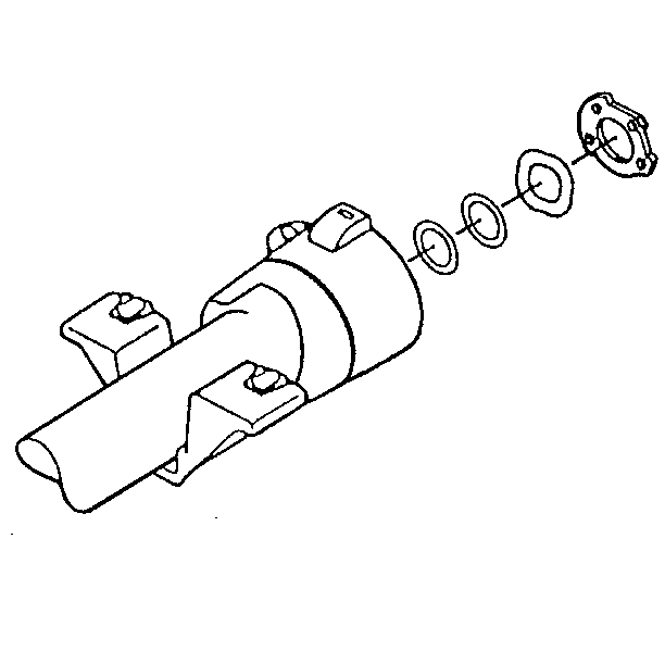
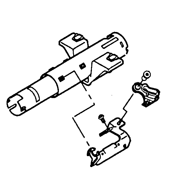
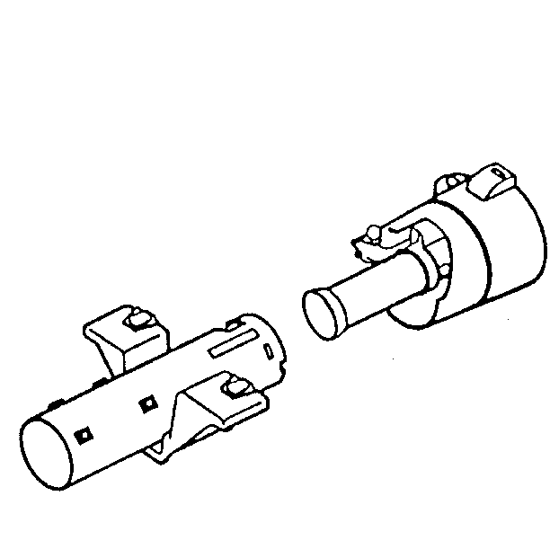
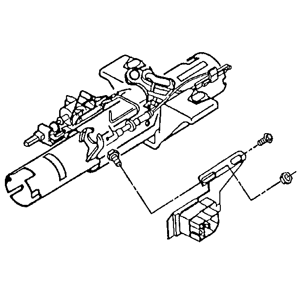
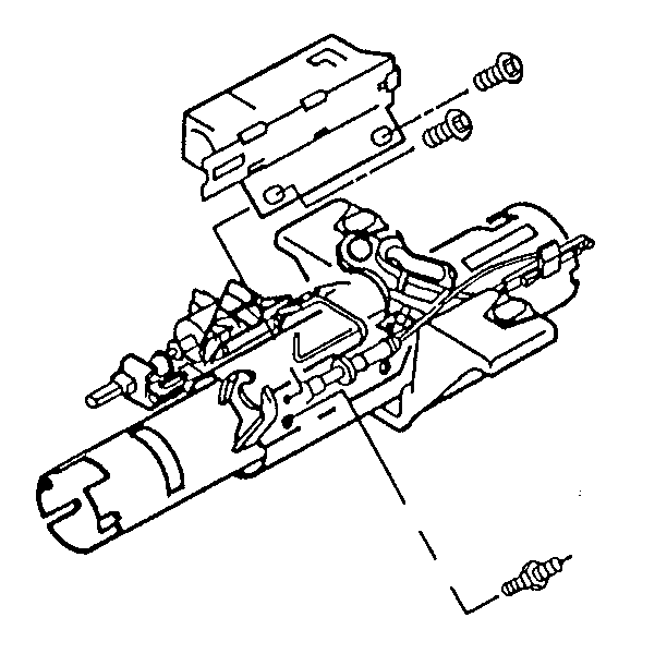
Important: The solenoid cable must remain straight, not kinked, during removal and installation.
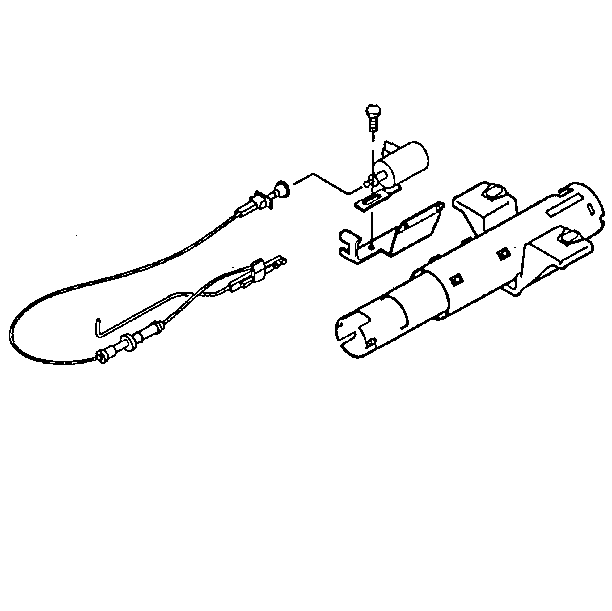
| 35.1. | Remove the cable mounting clip from the solenoid bracket assembly. |
| 35.2. | Remove the ball joint socket from the solenoid assembly. |
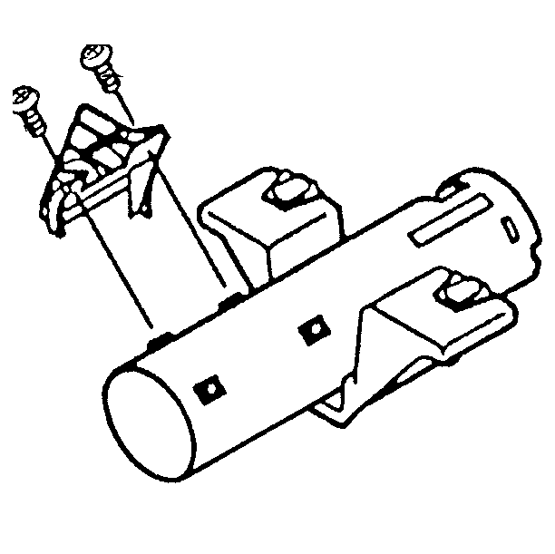
Installation Procedure
- Use the two lever support mounting screws to install the deflector plate and the solenoid bracket assembly.
- Install the interlock solenoid assembly to the bracket assembly using a hexagon head screw. At this time, only finger-tighten the hexagon head screw.
- Install the cable and actuator assembly to the interlock solenoid.
- Install the dimmer switch mounting stud.
- Use two washer head screws to install the ignition switch assembly.
- Connect the switch assembly and the cable and actuator assembly.
- Install the shift lever gate and the screws to the support.
- Attach the shift lever spring to the gearshift lever bowl assembly.
- Install the bowl to the shift tube assembly using J 23073-01 .
- Install the gearshift bowl shroud to the bowl.
- Attach the shift tube with bowl to the steering column jacket assembly.
- Install the two thrust washers.
- Install the wave washer using lithium grease.
- Install the lock plate.
- Install the two thrust washers.
- Install the shift tube retaining ring.
- Install the cable shift cam assembly.
- Install the cam retainer.
- Attach the dimmer switch rod to the column housing support assembly.
- Install the support assembly using new support screws.
- Install the steering shaft assembly to the jacket assembly. Lubricate with lithium grease.
- Attach the steering shaft collapse clip. The locking tabs must be installed into the holes in the lower steering shaft assembly.
- Install the inner race seat.
- Install the adapter and bearing assembly.
- Install the two hexagon washer head screws.
- Install the lower bearing seat.
- Install the lower bearing spring.
- Install the new lower spring retainer.
- Press the retainer onto the shaft to compress the spring.
- Measure the distance from the face of the adapter and bearing assembly to the lower spring retainer.
- Install the bearing and seal retainer.
- Install the tilt lever. Refer to Tilt Lever Replacement.
- Install the steering column housing assembly to the column.
- Position the column housing. Align the switch actuator rack with the pin on the end of the cable and actuator assembly.
- Pull back on the tilt lever while pushing the column housing assembly onto the column housing support assembly.
- Release the tilt lever to lock the shoes onto the dowel pins.
- Remove the tilt lever. Refer to Tilt Lever Replacement.
- Ensure that the tilt housing is set to the center position for standard columns.
- Install the pivot pins. Follow these steps when installing the pins.
- Install the steering column to the vehicle. Refer to Steering Column Replacement.
- Install the housing cover. Refer to Steering Column (Housing Cover).
- Install the upper column. Refer to Steering Column (Upper Column).
- Install the dimmer switch assembly. Refer to Dimmer Switch Assembly.
- Install the interlock solenoid assembly. Refer to Interlock Solenoid Assembly.
NOTICE: Ensure that all fasteners are securely seated before tightening to the specified torque value. Failure to do so may result in component damage or steering column malfunction.

Tighten
Tighten the lever support mounting screws to 4 N·m (35 lb in).
Notice: Use the correct fastener in the correct location. Replacement fasteners must be the correct part number for that application. Fasteners requiring replacement or fasteners requiring the use of thread locking compound or sealant are identified in the service procedure. Do not use paints, lubricants, or corrosion inhibitors on fasteners or fastener joint surfaces unless specified. These coatings affect fastener torque and joint clamping force and may damage the fastener. Use the correct tightening sequence and specifications when installing fasteners in order to avoid damage to parts and systems.

| 3.1. | Lubricate with grease the point at which the cable lug attaches to the switch actuator. |
| 3.2. | Attach the cable mounting clip to the solenoid bracket. |
| 3.3. | Install the ball joint socket to the solenoid. |

Tighten
Tighten the Torx washer head screw and the stud to 4 N·m
(35 lb in).

Tighten
Tighten the support screws to 3.7 N·m (33 lb in).

Important: The thrust washers must be assembled face-to-face with teflon coatings. Improper assembly will cause steering failure.


Tighten
Tighten the cam retainer to 4 N·m (35 lb in).
Important: Support screws require thread locking compound.


Tighten
Tighten the new support screws to 10 N·m (89 lb in).
Tighten
Tighten the two hexagon washer head screws to 3.4 N·m (30 lb in).

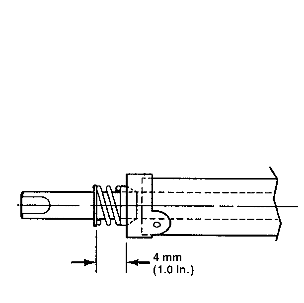
The spring height must equal 25.4 mm (1.0 in).

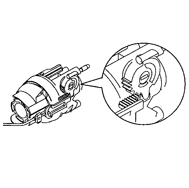
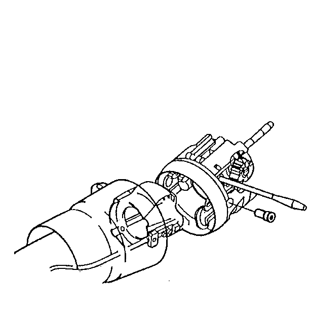

| • | Lubricate the pins with lithium grease |
| • | Press the pin until it is firmly seated in two places |
| • | Stake the pins in three places |
Steering Column Replacement Housing Assembly
Disassembly Procedure
Tools Required
J 22635 Lock Shoe and Release Lever Pin Remover and Installer
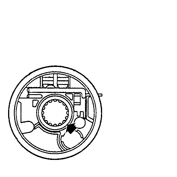
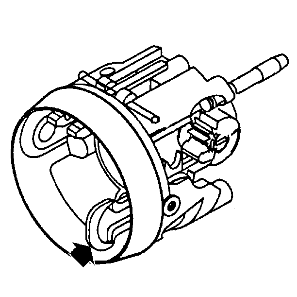
- Disassemble the bearing assembly.
- Disassemble the switch actuator rack and the rack preload spring.
- Disassemble the release lever spring.
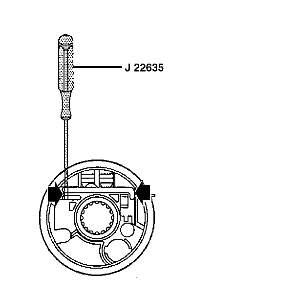
- Disassemble the shoe release lever using J 22635 .
- Disassemble the release lever spring.
- Remove the dowel pin using J 22635 .
- Disassemble the lock shoes.
- Disassemble the shoe springs.
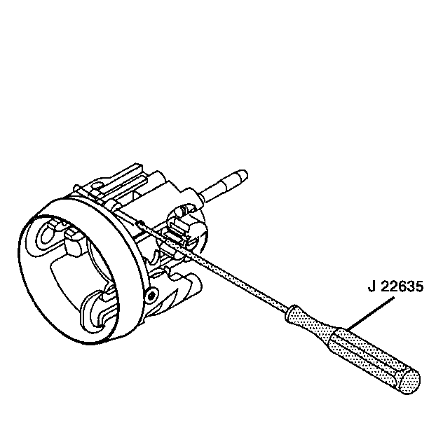

Assembly Procedure
Tools Required
| • | J 22635 Lock Shoe and Release Lever Pin Remover and Installer |
| • | J 8092 Driver Handle |
| • | J 38639 Steering Column Housing Bearing Installer |
- Assemble the shoe springs.
- Assemble the lock shoes.
- Insert the dowel pin using J 22635 .
- Assemble the release lever spring.
- Assemble the shoe release lever.
- Attach the release lever pin using J 22635 .
- Assemble the rack preload spring.
- Assemble the switch actuator rack to the actuator sector.
- Use J 38639 and J 8092 to assemble the bearing assembly to the column housing. Lubricate with lithium grease.


Steering Column Replacement Shaft Assembly
Disassemble Procedure
- Disassemble the race and upper shaft assembly and the lower steering shaft assembly.
- Disassemble the center sphere from the upper shaft assembly.
- Disassemble the joint preload spring from the centering sphere.
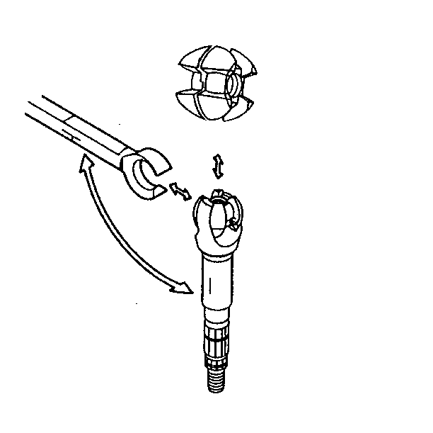
In order to disengage the assemblies, tilt them 90 degrees toward each other and disengage.
Rotate the sphere 90 degrees and slip the sphere out.
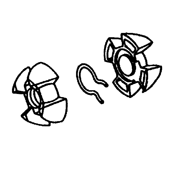
Assemble Procedure
- Assemble the joint preload spring to the two centering sphere halves.
- Assemble the centering sphere by following these steps:
- Assemble the race and upper shaft assembly to the lower steering shaft assembly.


| 2.1. | Lubricate the sphere with lithium grease |
| 2.2. | Slip the sphere into the upper shaft assembly |
| 2.3. | Rotate the sphere 90 degrees |
Line up the marks and tilt the assemblies 90 degrees toward each other.
Steering Column Replacement Lower Column-Column Shift
Removal Procedure
- Disconnect the negative battery cable.
Refer to
Caution: Unless directed otherwise, the ignition and start switch must be in the OFF or LOCK position, and all electrical loads must be OFF before servicing any electrical component. Disconnect the negative battery cable to prevent an electrical spark should a tool or equipment come in contact with an exposed electrical terminal. Failure to follow these precautions may result in personal injury and/or damage to the vehicle or its components.
in General Information. - Remove the steering column from the vehicle. Refer to Steering Column Replacement.
- Inspect the steering column for accident damage. Refer to Inspection Required After an Accident.
- Remove the bearing and the seal retainer.
- Remove and discard the lower spring retainer.
- Remove the lower bearing spring.
- Remove the lower bearing seat.
- Remove the two hexagon washer head screws.
- Remove the adapter and the bearing assembly.
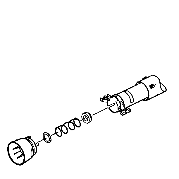
NOTICE: Once the steering column has been removed from the vehicle, it is extremely susceptible to damage. Dropping the steering column on its end could collapse the steering shaft or loosen the plastic injections which maintain column rigidity. Leaning on the steering column assembly could cause the jacket to bend or deform. Any of the above damage could impair the column's collapsible design. Use only the specified steering wheel puller to remove the steering wheel. Under no conditions should the end of the shaft be hammered on as hammering could loosen the plastic injections which maintain column rigidity.
Important: Use only the specified steering wheel puller to remove the steering wheel. Under no conditions should the end of the shaft be hammered on as this could loosen the plastic injections which maintain the steering column's rigidity.
Installation Procedure
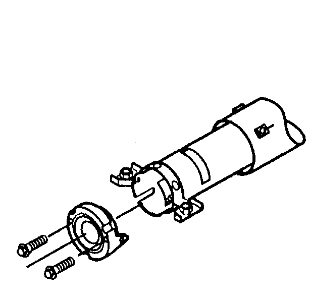
- Install the adapter and bearing assembly. Lubricate the inner surface with lithium grease.
- Install the two hexagon washer head screws.
- Install the lower bearing seat.
- Install the lower bearing spring.
- Install a new lower spring retainer.
- Measure the distance from the face of the adapter and the bearing assembly to the lower spring retainer. The spring height must equal 25.4 mm (1 in).
- Install the bearing retainer.
- Install the steering column to the vehicle. Refer to Steering Column Replacement.
- Connect the negative battery cable.
NOTICE: Ensure that all fasteners are securely seated before tightening to the specified torque value. Failure to do so may result in component damage or steering column malfunction.

Tighten
Tighten the washer head screws to 3.4 N·m (30 lb in).
Notice: Use the correct fastener in the correct location. Replacement fasteners must be the correct part number for that application. Fasteners requiring replacement or fasteners requiring the use of thread locking compound or sealant are identified in the service procedure. Do not use paints, lubricants, or corrosion inhibitors on fasteners or fastener joint surfaces unless specified. These coatings affect fastener torque and joint clamping force and may damage the fastener. Use the correct tightening sequence and specifications when installing fasteners in order to avoid damage to parts and systems.

Press the retainer onto the steering shaft in order to compress the spring.


