For 1990-2009 cars only
Removal Procedure
Tools Required
| • | J 25008-A Holding Fixture |
| • | J 33013-B Clutch Plate and Hub Assembly Remover |
- If the compressor is on the vehicle, complete the following steps before proceeding:
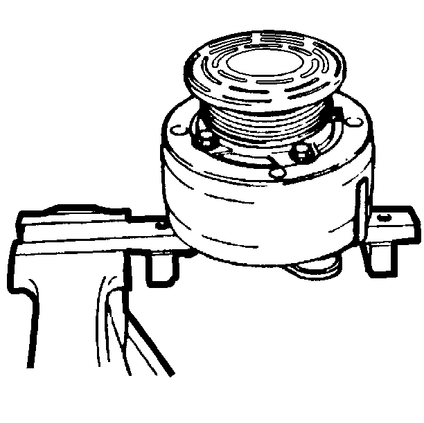
- If the compressor is not on the vehicle, attach the compressor to the J 25008-A .
- Clamp the J 25008-A in a vise.
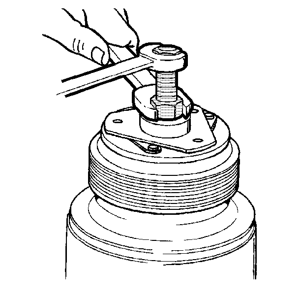
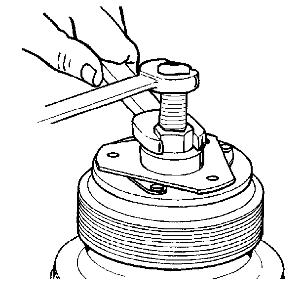
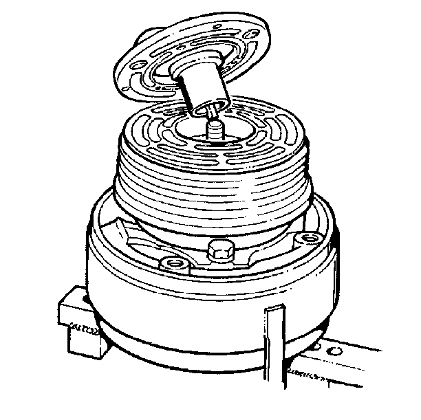
- Thread the J 33013-B onto the hub.
- Hold the body of the remover with a wrench and turn the center screw into the remover body.
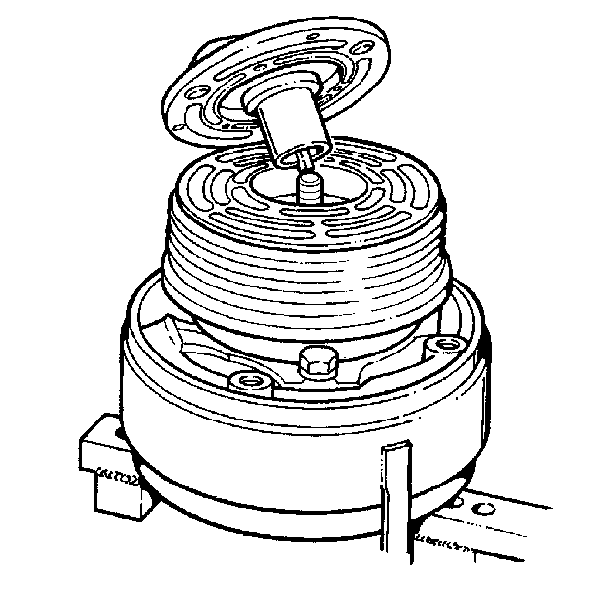
- Remove the clutch plate and hub assembly.
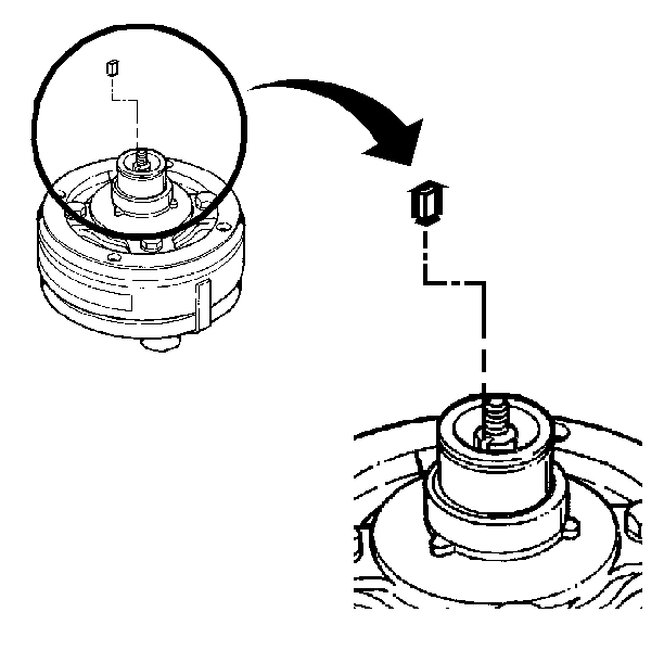
- Remove the shaft key.
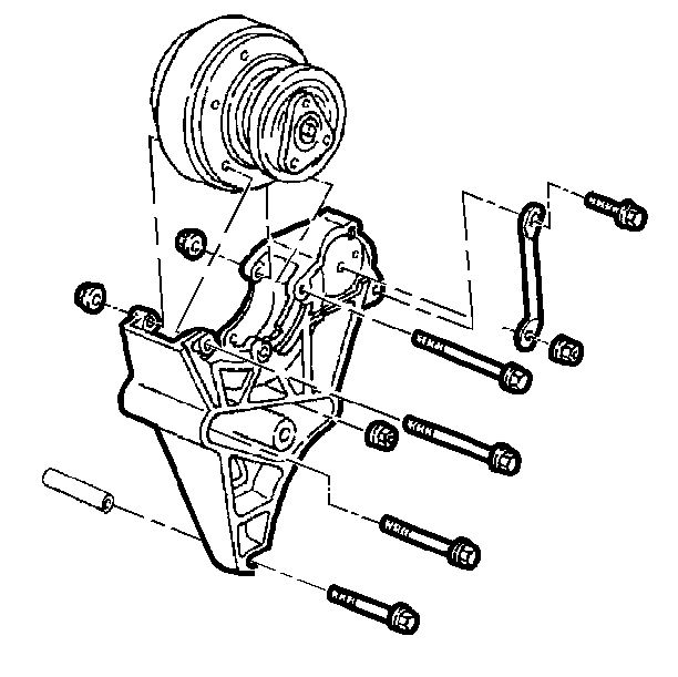
| • | Loosen the compressor mounting brackets. |
| • | Reposition the compressor for easier access. |
| • | Disconnect the compressor drive belt. Refer to Drive Belt Diagnosis in Engine Cooling. |
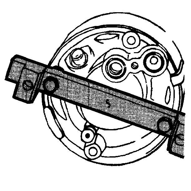
Important: The compressor mounting bolts are metric. Use the proper metric bolts when using the J 25008-A .
Installation Procedure
Tools Required
J 9401-B Clutch Plate and Hub Installer
- Install the shaft key into the hub key groove.
- Ensure that the frictional surface of the clutch plate and clutch rotor are clean before installing the clutch plate and hub assembly.
- Align the shaft key with the shaft keyway.
- Place the clutch plate and hub assembly onto the compressor shaft.
- Install the J 9401-B .
- Use a wrench in order to hold the hex portions of the J 9401-B . Tighten the center screw until there is a 0.4-0.5 mm (0.015-0.020 in) air gap between the frictional surface of the clutch plate and the clutch rotor.
- If the compressor is on the vehicle, connect the drive belt and adjust the belt tension. Refer to Drive Belt Diagnosis in Engine Cooling.
- Tighten the mounting brackets.
Notice: In order to avoid internal damage to the compressor do not drive or pound on the clutch hub or the shaft.

| • | Allow the key to project approximately 4.8 mm (3/16 in) out of the keyway. |
| • | The shaft key is slightly curved in order to provide an interference fit in the shaft key groove of the hub. |
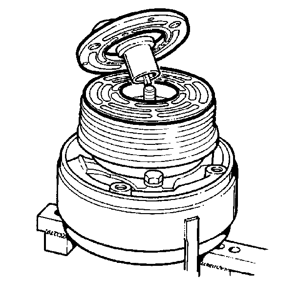
Important: Ensure that the shaft key is even or slightly above the clutch hub.
