For 1990-2009 cars only
Removal Procedure
Tools Required
| • | J 4245 Snap Ring Pliers #21 Internal |
| • | J 9553-01 o-ring Remover |
- Recover the refrigerant. Refer to Refrigerant Recovery and Recharging .
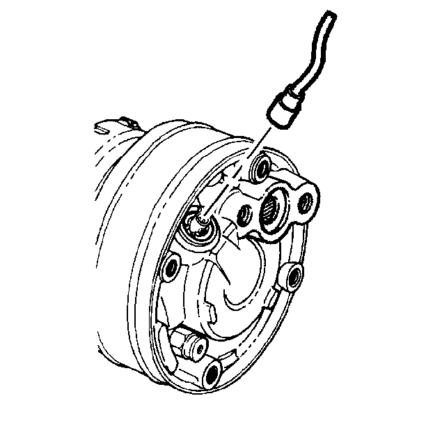
- Disconnect the electrical connector from the switch.
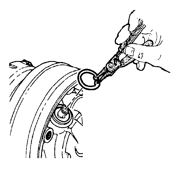
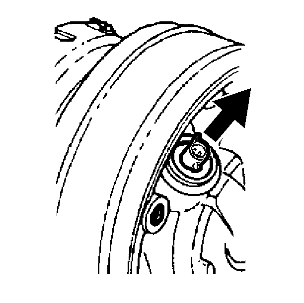
- Use the J 4245 in order to remove the switch retainer ring.
- Pull the terminal housing in order to remove the switch from the compressor.
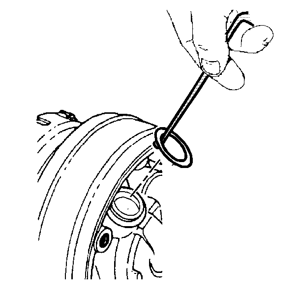
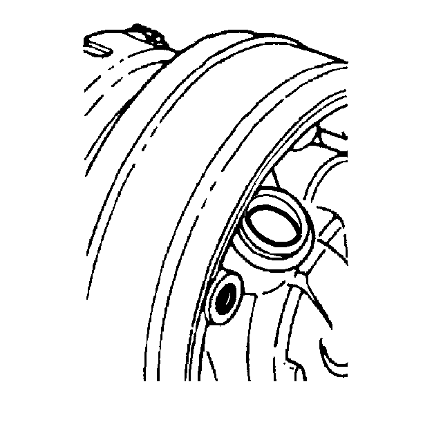
- Use the J 9553-01 in order to remove the O-ring from the switch cavity.
Installation Procedure
Tools Required
J 4245 Snap Ring Pliers #21 Internal
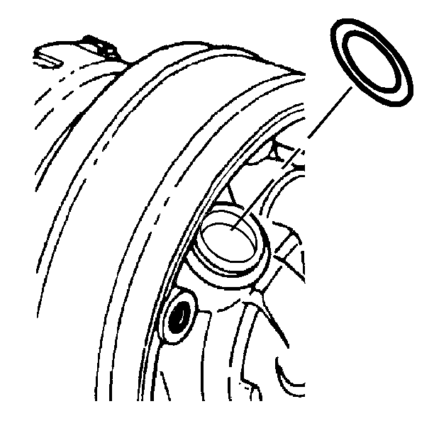
- If reinstalling the switch to the compressor, use a new O-ring.
- Ensure that the switch cavity and the O-ring groove are free of dirt or foreign material. Clean as necessary.
- Install the O-ring into the groove in the switch cavity. Coat the new O-ring with 525 viscosity refrigerant oil prior to installation.
- Insert the switch into the switch cavity.
- Use the J 4245 in order to install the retainer ring.
- Connect the electrical connector to the switch.
- Evacuate the system. Refer to Evacuation .
- Charge the system. Refer to A/C Charging Using ACR4 .
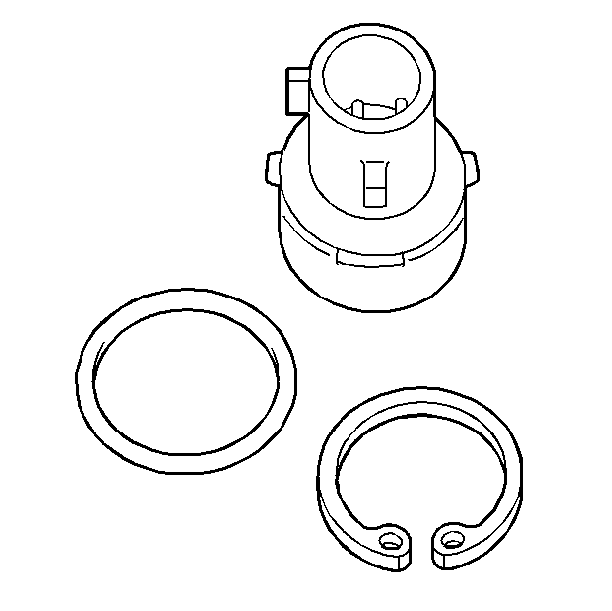
| • | It is preferable to use a new retainer ring. |
| • | A new switch kit contains both the O-ring and the retainer ring. |
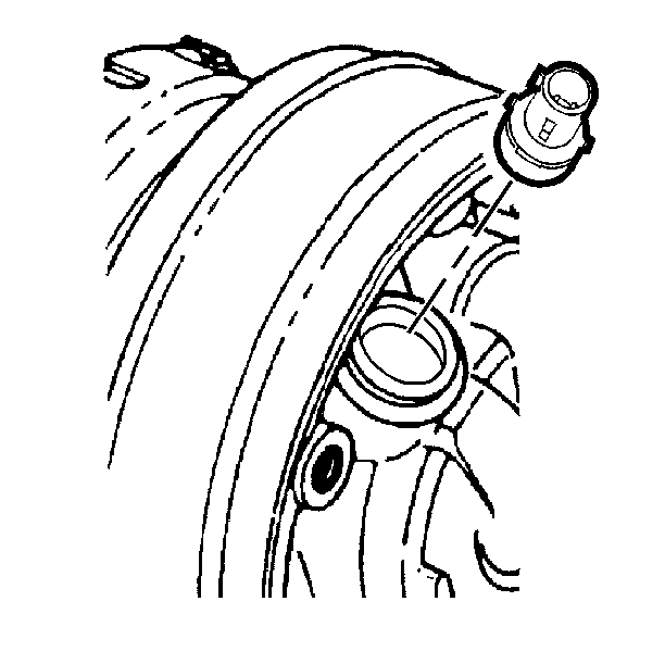
| • | Coat the switch housing with 525 viscosity refrigerant oil prior to installation. |
| • | Ensure that the switch touches the bottom of the cavity. |

| • | Ensure that the highest point of the curved sides are adjacent to the switch housing. |
| • | Ensure that the retainer ring is properly seated in the switch cavity retainer ring groove. |

