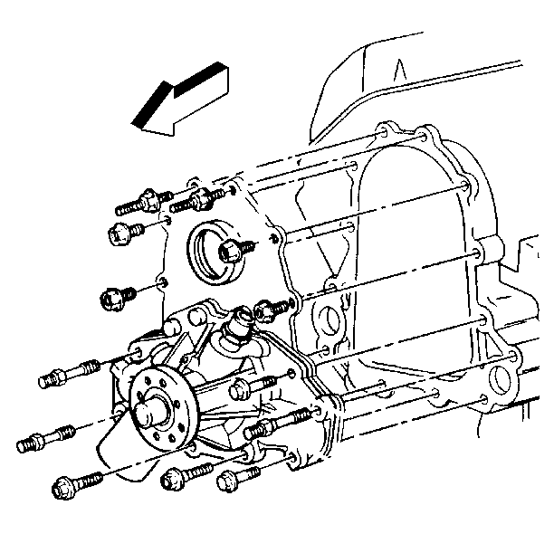
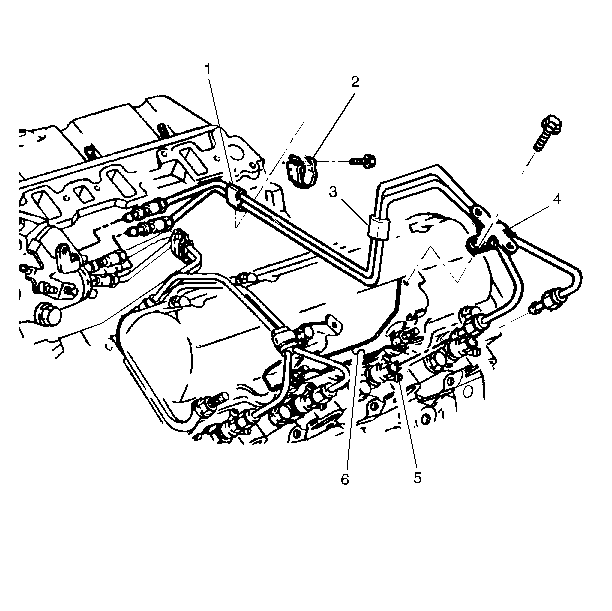
Removal Procedure
- Remove the intake manifold. Refer to Intake Manifold Replacement.
- Remove the injection lines.
- Remove the bleed valve from the coolant crossover pipe.
- Mark or scribe the injector pump to the front cover for installation.
- Disconnect the fuel crossover line from the front cover.
- Remove the oil fill tube assembly.
- Remove the vacuum pump (if equipped). Refer to Vacuum Pump Replacement in Vacuum Pumps.
- Remove the coolant pump. Refer to Coolant Pump Replacement in Engine Cooling.
- Remove the torsional damper. Refer to Crankshaft Balancer Replacement.
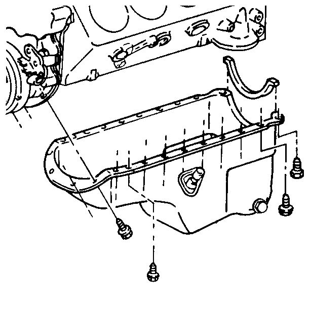
- Remove the four oil pan bolts from the front cover.
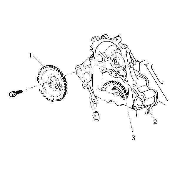
- Align the injector pump gear and camshaft gear marks.
- Remove the injector pump gear.
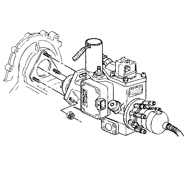
- Remove the three bolts holding the injector pump to the front cover. Pull the pump out of the cover. Lay the pump on the engine block.
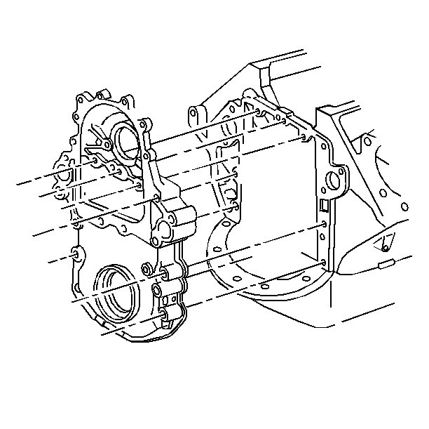
- Remove the remaining front cover bolts and the baffle, if equipped.
- Remove the front cover.
- Remove and discard the seal from the front cover.
- Clean the RTV from the oil pan sealing surface.
- Clean the sealing surfaces on the front cover.
- Inspect the front cover sealing surfaces for cracks or damage.

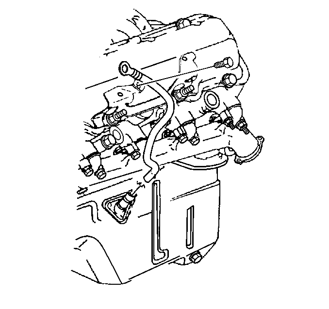
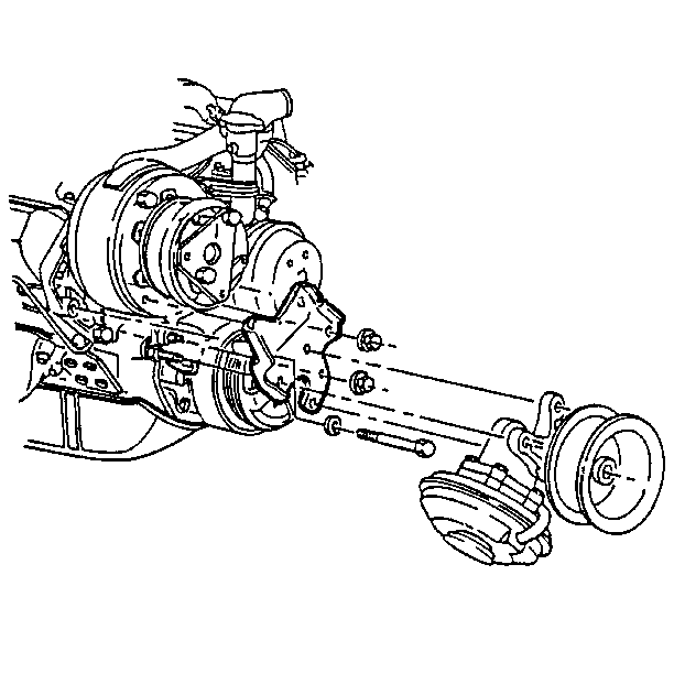
Installation Procedure
Tools Required
J 22102 Seal Installer
- Install a new front crankshaft seal to the front cover using J 22102 .
- Apply a 2 mm (3/32 in) bead of anaerobic sealant (GM P/N 1052357 or the equivalent) to the front cover sealing area.
- Apply a 5 mm (3/16 in) bead of RTV sealant (GM P/N 1052915 or the equivalent) to the front cover sealing surface that mates against the oil pan.
- Install the front cover and the attaching bolts to the engine.
- Install the baffle, if equipped.
- Align the scribe marks on the front cover and the injection pump.
- Install the injection pump and the nuts.
- Install the injection pump gear bolts. Align the timing marks.
- Measure the clearance between the injection pump gear and the baffle, if equipped.
- Attach the front cover plate to the pump.
- Install the coolant pump. Refer to Coolant Pump Replacement in Engine Cooling.
- Install the torsional damper. Refer to Crankshaft Balancer Replacement.
- Install the vacuum pump. Refer to Vacuum Pump Replacement in Vacuum Pumps.
- Connect the fuel crossover line to the front cover.
- Install the oil fill tube to the front cover.
- Attach the injector lines to the fuel injectors.
- Connect the injector lines to the mounting clamps at the valve covers.
- Install the intake manifold. Refer to Intake Manifold Replacement.
- Fill the coolant system. Refer to Draining, Filling, Recovery of Cooling System in Engine Cooling.
- Connect the negative battery cable.
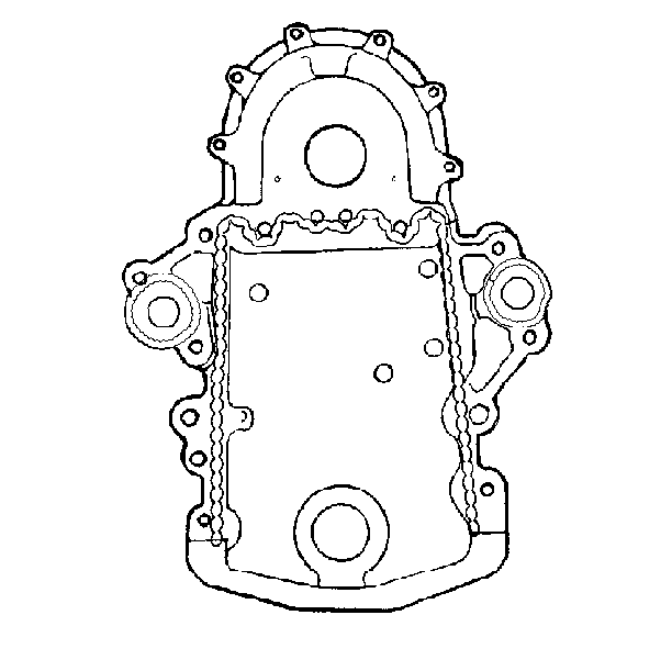
The sealer must be wet to the touch when the bolts are torqued.

Tighten
Tighten the front cover bolts to 45 N·m (33 lb ft).
Notice: Use the correct fastener in the correct location. Replacement fasteners must be the correct part number for that application. Fasteners requiring replacement or fasteners requiring the use of thread locking compound or sealant are identified in the service procedure. Do not use paints, lubricants, or corrosion inhibitors on fasteners or fastener joint surfaces unless specified. These coatings affect fastener torque and joint clamping force and may damage the fastener. Use the correct tightening sequence and specifications when installing fasteners in order to avoid damage to parts and systems.

Tighten
Tighten the oil pan to the front cover bolts to 10 N·m
(89 lb in).
Tighten
Tighten the baffle bolts and nut to 45 N·m (33 lb ft).

Tighten
Tighten the nuts to 42 N·m (31 lb ft).

Tighten
Tighten the injection pump gear bolts to 23 N·m (17 lb ft).
Maintain a minimum clearance of 1.0 mm (0.040 in) between the gear and the baffle or noise may result.
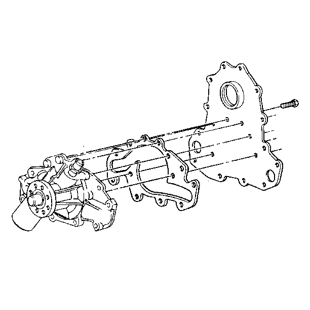
Tighten
Tighten the bolts to 45 N·m (33 lb ft).
