GM Service Manual Online
For 1990-2009 cars only

Removal Procedure


    Object Number: 43237  Size: SH
  1. Remove the intake manifold. Refer to Intake Manifold Replacement.
  2. Disconnect the injection lines.

  3. Object Number: 43235  Size: SH
  4. Remove the rocker arm covers. Refer to Valve Rocker Arm Cover Replacement.
  5. Drain the cooling system. Refer to Draining, Filling Recovery of the Cooling System in Engine Cooling.
  6. Raise the vehicle. Support the vehicle with safety stands.

  7. Object Number: 42798  Size: SH
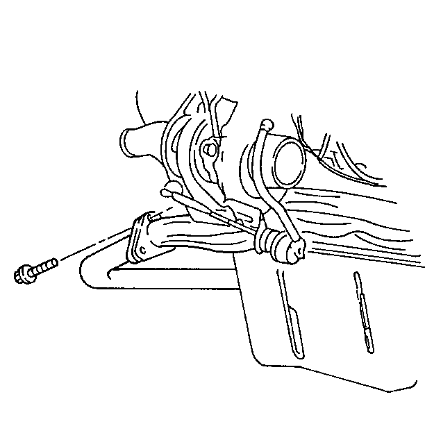
  8. Remove the exhaust pipe from the manifold and the turbocharger (if equipped, left side).
  9. Lower the vehicle.

  10. Object Number: 22109  Size: SH
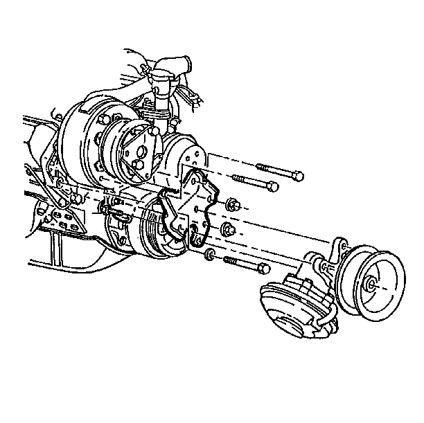
  11. Remove the air conditioning compressor and the bracket from the left cylinder head. Lay them aside.

  12. Object Number: 22112  Size: SH
  13. Remove and lay aside the following components from the left cylinder head.
  14. • The vacuum pump (if equipped) and bracket
    • The ground strap
    • The turbocharger

    Object Number: 24339  Size: SH
  15. Remove and lay aside the following components from the right cylinder head.
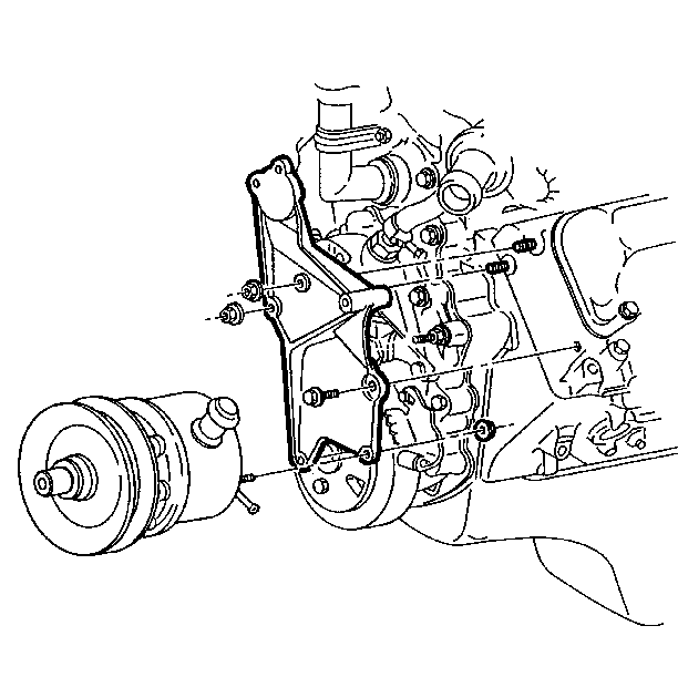
  16. • The power steering pump
    • The generator and the rear bracket
    • The right side engine accessory bracket

    Object Number: 43227  Size: SH
  17. Remove these three remaining components from the right cylinder head.
  18. • The wiring harness at the clips
    • The glow plug relay
    • The dipstick tube

    Object Number: 43230  Size: SH
  19. Disconnect the wire from the coolant sensor at the cylinder head.
  20. Disconnect the glow plug wires.
  21. Important: The rocker arm assemblies and the pushrods must be marked for proper assembly.


    Object Number: 43214  Size: SH
  22. Remove the rocker arm assemblies and the pushrods. Refer to Rocker Arm and Pushrod Replacement.

  23. Object Number: 26589  Size: SH
  24. Remove the radiator, the bypass, and the heater hoses.
  25. Remove the ground straps.
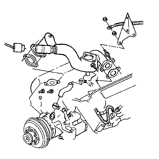
  26. Remove the coolant crossover pipe/thermostat housing assembly.

  27. Object Number: 43231  Size: SH
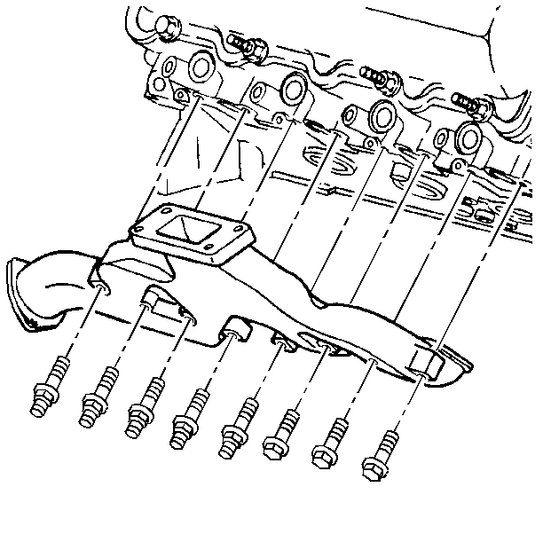
  28. Remove the exhaust manifold.

  29. Object Number: 43245  Size: SH
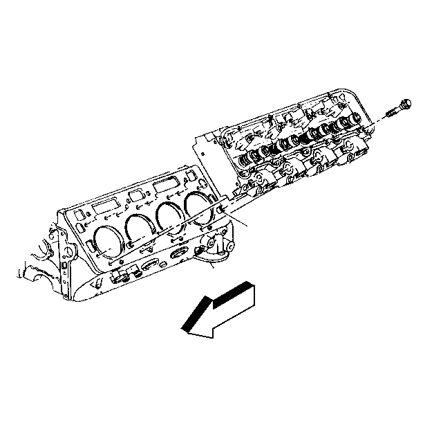
  30. Remove the cylinder head bolts.
  31. The rear bolt in the left cylinder head may have to remain in the head during removal.

  32. Remove the cylinder head.

  33. Object Number: 43335  Size: SH
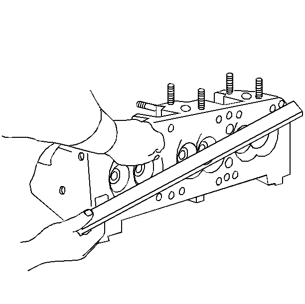
  34. Measure the cylinder head for warping.
  35. If the head is warped more than 0.15 mm (0.006 in) longitudinally or 0.08 mm (0.003 in) transversely, replace the cylinder head. Resurfacing is not recommended.

  36. Measure the pre-chamber installed depth.
  37. 22.1. Make the measurement at two or more points on the pre-chamber where the pre-chamber seats on the head gasket shield and sealing ring.
    22.2. Measure the difference between the flat of the pre-chamber and the flat surface of the cylinder head.
    22.3. The pre-chamber must not protrude out of the cylinder head more than 0.05 mm (0.002 inch).
    22.4. The pre-chamber must not be recessed into the cylinder head.

Cleaning Procedure

   • 
Object Number: 4957  Size: SH
  • Clean off any carbon deposits from the combustion chambers.
  •    • 
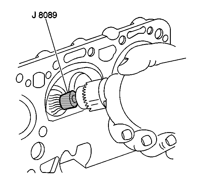
  • Remove all traces of old head gasket from the cylinder head and the block. Do not use a motorized wire brush.
  •    • 
  • Clean the cylinder head bolt threads using a wire brush.
  •    • 
  • Remove any metal chips and dirt from the threads in the block.
  • Inspection Procedure

        • Inspect the cylinder head for cracks between the intake and exhaust ports. Use the magnaflux or dye methods if available.
        • Examine the sealing surfaces of the block and the cylinder head for nicks, heavy scratches, or other damage.
        • Check the block for missing or damaged dowel pins or for dowel pins in the wrong location.

    Installation Procedure

      Important: The block gasket surfaces must be clean. Do not use a sealer on the head gasket. The head gasket is manufactured with the proper amount of sealant printed on its surface. Additional sealer may cause leakage or malfunction. Some sealers may attack the sealant already on the head gasket.


      Object Number: 43339  Size: SH
    1. Install the head gasket to the block over the dowel pins.
    2. Install the rear cylinder head bolt to the left cylinder head.
    3. Apply sealant (GM P/N 9985283 or the equivalent) to the bolt threads and under the bolt threads. Due to clearances, the bolt must be installed at this time.

    4. Guide the cylinder head carefully into place over the dowel pins in order to install the cylinder head. The gasket surfaces must be clean.

    5. Object Number: 43340  Size: SH
    6. Install the cylinder head bolts.
    7. Make sure the bolt threads are clean.
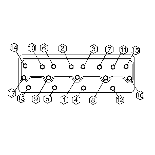

      Object Number: 43341  Size: SH
    8. Apply sealant (GM P/N 9985283 or the equivalent) to the bolt threads and under the bolt threads.
    9. Tighten
      Tighten the cylinder head bolts to 25 N·m (20 lb ft).

      Notice: Use the correct fastener in the correct location. Replacement fasteners must be the correct part number for that application. Fasteners requiring replacement or fasteners requiring the use of thread locking compound or sealant are identified in the service procedure. Do not use paints, lubricants, or corrosion inhibitors on fasteners or fastener joint surfaces unless specified. These coatings affect fastener torque and joint clamping force and may damage the fastener. Use the correct tightening sequence and specifications when installing fasteners in order to avoid damage to parts and systems.

      Tighten
      Tighten all the bolts in sequence to 65 N·m (50 lb ft).

      Tighten
      Tighten all the bolts in sequence an additional 90-100 degrees (1/4+ turn).

      Object Number: 26589  Size: SH
    10. Install the coolant crossover pipe/thermostat assembly with the bolts and new gaskets.
    11. Tighten
      Tighten the bolts to 42 N·m (31 lb ft).

    12. Install the ground strap.
    13. Install the radiator, the bypass, and the heater hoses.
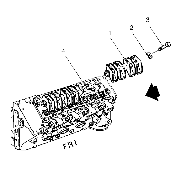
    14. Important: Return all rocker arm assemblies and pushrods to their original locations.

      Object Number: 43214  Size: SH
    15. Install the pushrods and the rocker arm assemblies. The hardened ends of the pushrods must face up. Refer to Rocker Arm and Pushrod Replacement.
    16. Object Number: 43233  Size: SH
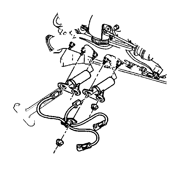
    17. Connect the glow plug wires.
    18. Connect the wire from the coolant sensor at the cylinder head.
    19. Object Number: 22109  Size: SH
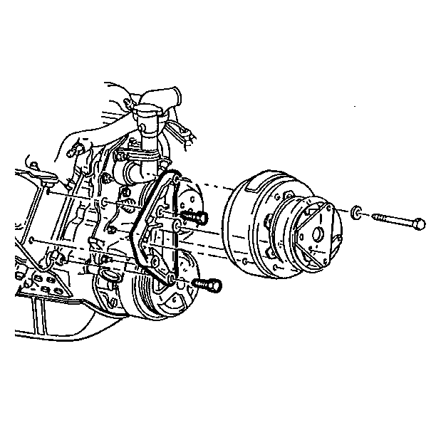
    20. Install the following components on the left cylinder head.
    21. • The air conditioning compressor and bracket
      • The ground strap
      • The turbocharger

      Object Number: 24339  Size: SH
    22. Install the following components on the right cylinder head.
    23. • The power steering pump
      • The generator and the rear bracket
      • The right side engine accessory bracket

      Object Number: 43227  Size: SH
    24. Install these three remaining components on the right cylinder head.
    25. • The wiring harness at the clips
      • The glow plug relay
      • The dipstick tube

      Object Number: 42798  Size: SH
    26. Raise the vehicle. Support the vehicle with safety stands.
    27. Install the exhaust pipe to the manifold.
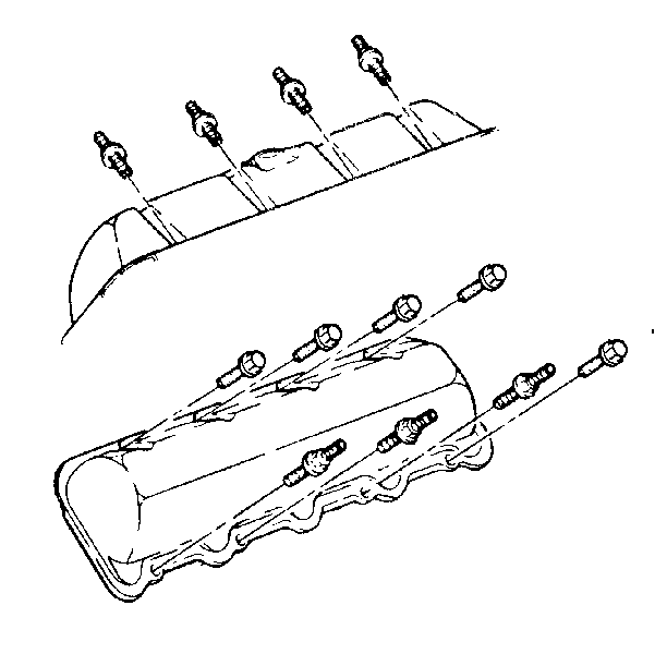
    28. Object Number: 43235  Size: SH
    29. Lower the vehicle.
    30. Install the rocker arm covers. Refer to Valve Rocker Arm Cover Replacement.

    31. Object Number: 43237  Size: SH
    32. Connect the injection lines.
    33. Install the intake manifold. Refer to Intake Manifold Replacement.
    34. Fill the cooling system with the proper quantity and grade of coolant.