Wheel Bearing Adjustment Grease Lubricated
Removal Procedure
- Raise the vehicle. Support the vehicle with suitable safety stands.
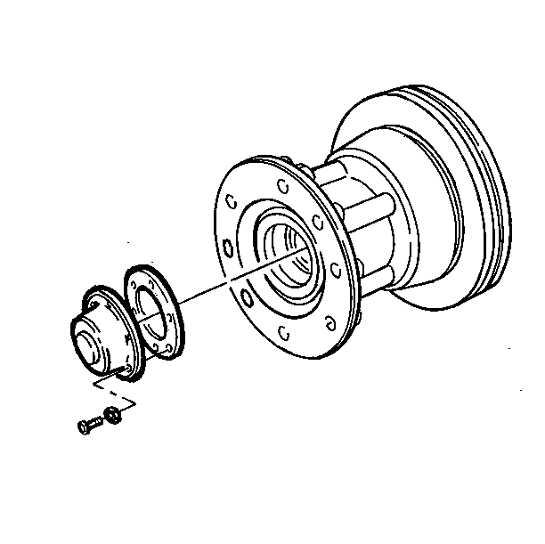
- Remove the bolts and the washers.
- Remove the hub cap and the gasket. Do not allow gasket material to fall into the hub.
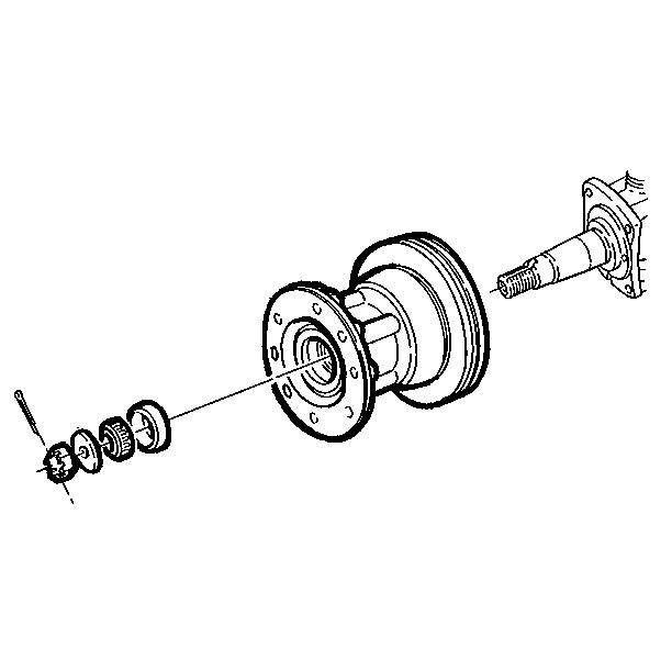
- Remove the cotter pin.

Adjustment Procedure
- Tighten the adjusting nut while you rotate the wheel 360 degrees in both directions in order to correctly position the bearings.
- Back off the nut 1/6 turn or more until the slot in the nut lines up with the hole in the spindle.

Tighten
Tighten the adjusting nut to 153 N·m (113 lb ft).
Notice: Use the correct fastener in the correct location. Replacement fasteners must be the correct part number for that application. Fasteners requiring replacement or fasteners requiring the use of thread locking compound or sealant are identified in the service procedure. Do not use paints, lubricants, or corrosion inhibitors on fasteners or fastener joint surfaces unless specified. These coatings affect fastener torque and joint clamping force and may damage the fastener. Use the correct tightening sequence and specifications when installing fasteners in order to avoid damage to parts and systems.
Important: Always back off the nut a minimum of 1/6 of a turn. This adjustment should result in bearing end play of 0.025-0.020 mm (0.001-0.008 in).
Installation Procedure
- Install the new cotter pin.
- Install the new gasket and the hub cap. Make sure the gasket is properly aligned.
- Install the bolts and the new washers.
- Remove the safety stands. Lower the vehicle.

Tighten
Tighten the bolts evenly to 13 N·m (115 lb in).
Notice: Use the correct fastener in the correct location. Replacement fasteners must be the correct part number for that application. Fasteners requiring replacement or fasteners requiring the use of thread locking compound or sealant are identified in the service procedure. Do not use paints, lubricants, or corrosion inhibitors on fasteners or fastener joint surfaces unless specified. These coatings affect fastener torque and joint clamping force and may damage the fastener. Use the correct tightening sequence and specifications when installing fasteners in order to avoid damage to parts and systems.
Wheel Bearing Adjustment Oil Lubricated
Removal Procedure
- Raise the vehicle. Support the vehicle with suitable safety stands.
- Remove the bolts and the washers.
- Remove the hub cap and the gasket. Do not allow the gasket material to fall into the hub.
- Remove the cotter pin.

Adjustment Procedure
- Tighten the adjusting nut while you rotate the wheel 360 degrees in both directions in order to correctly position the bearings.
- Back off the nut 1/6 turn or more until the slot in the nut lines up with the hole in the spindle.

Tighten
Tighten the adjusting nut to 153 N·m (113 lb ft).
Notice: Use the correct fastener in the correct location. Replacement fasteners must be the correct part number for that application. Fasteners requiring replacement or fasteners requiring the use of thread locking compound or sealant are identified in the service procedure. Do not use paints, lubricants, or corrosion inhibitors on fasteners or fastener joint surfaces unless specified. These coatings affect fastener torque and joint clamping force and may damage the fastener. Use the correct tightening sequence and specifications when installing fasteners in order to avoid damage to parts and systems.
Important: Always back off the nut a minimum of 1/6 of a turn. This adjustment should result in bearing end play of 0.025-0.020 mm (0.001-0.008 in).
Installation Procedure
- Install the new cotter pin.
- Install the new gasket and the hub cap. Make sure the gasket is properly aligned.
- Install the bolts and the new washers.
- If the oil level in the hubs is not at or above the 6 mm (1/4 in) oil level line, remove the pipe plug or rubber window plug.
- Add lubricant until the level is at or above the oil level line.
- Remove the safety stands. Lower the vehicle.

Tighten
Tighten the bolts evenly to 13 N·m (115 lb in).
Notice: Use the correct fastener in the correct location. Replacement fasteners must be the correct part number for that application. Fasteners requiring replacement or fasteners requiring the use of thread locking compound or sealant are identified in the service procedure. Do not use paints, lubricants, or corrosion inhibitors on fasteners or fastener joint surfaces unless specified. These coatings affect fastener torque and joint clamping force and may damage the fastener. Use the correct tightening sequence and specifications when installing fasteners in order to avoid damage to parts and systems.
