For 1990-2009 cars only
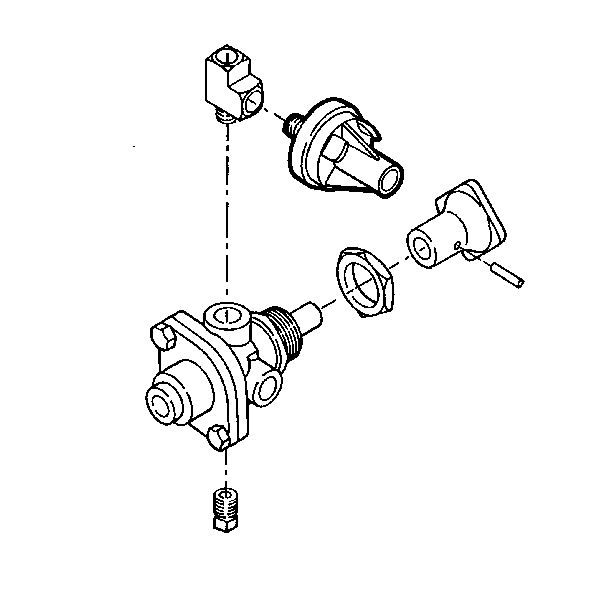
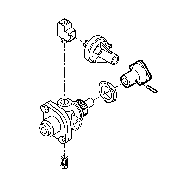
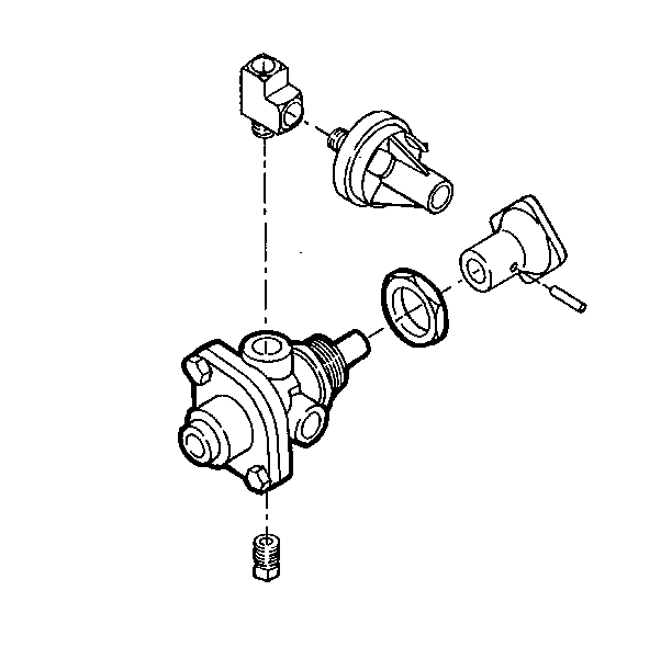
Park Brake Solenoid Valve Replacement Gen.
Removal Procedure
- Block the vehicle's wheels.
- Drain all the air reservoirs.
- Disconnect the air lines from the valve. Tag or label the air lines for later installation.
- Remove the pressure sensor. Refer to Parking Brake Pressure Sensor.
- Remove the pin.
- Remove the knob.
- Remove the nut.
- Remove the valve.
- Inspect the air lines for damage or deterioration. Repair as needed.
- Inspect for cracked, loose, or missing line clips or ties. Repair as needed.


Installation Procedure
- Install the valve.
- Install the nut.
- Install the knob.
- Install the pin.
- Install the air lines in the following order:
- Install the pressure sensor. Refer to Parking Brake Pressure Sensor.
- Perform Leakage Test. Refer to Park Brake Valve .
- Perform Operational Check. Refer to Park Brake Valve .
- Check the operation of the brakes.
- Remove the wheel blocks.


| 5.1. | Delivery port air line |
| 5.2. | Supply port air line |
| 5.3. | Exhaust port air line |
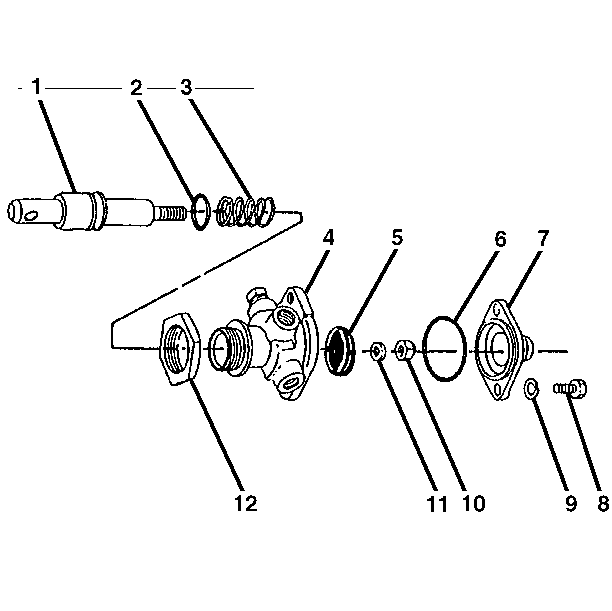
Park Brake Solenoid Valve Replacement Air Parking Brake
Removal Procedure
- Remove the bolts (8) and the washers (9).
- Remove the cover (7) and the O-ring seal (6).
- Remove the nut (10).
- Remove the washer (11).
- Remove the valve (5).
- Remove the plunger (1).
- Remove the O-ring seal (2)
- Remove the spring (3).
- Remove the mounting nut (12).
- Clean all the metal parts in mineral spirits or another suitable solvent.
- Inspect the plunger and the valve bore for scoring and burrs. Replace if necessary.

Installation Procedure
- Lubricate the valve bores, the plunger, the valve and the O-ring seal with a thin film of Delco Silicone Lube (GM P/N 18010909) or the equivalent.
- Install the O-ring seal (2) on the plunger (1).
- Install the spring (3) and the plunger in the body (4).
- Install the mounting nut (12).
- Install the valve (5).
- Install the washer (11).
- Install the nut (10).
- Install the O-ring seal (6) and the cover (7).
- Install the washers (9) and the bolts (8).

Use only new seals from the repair kit.
