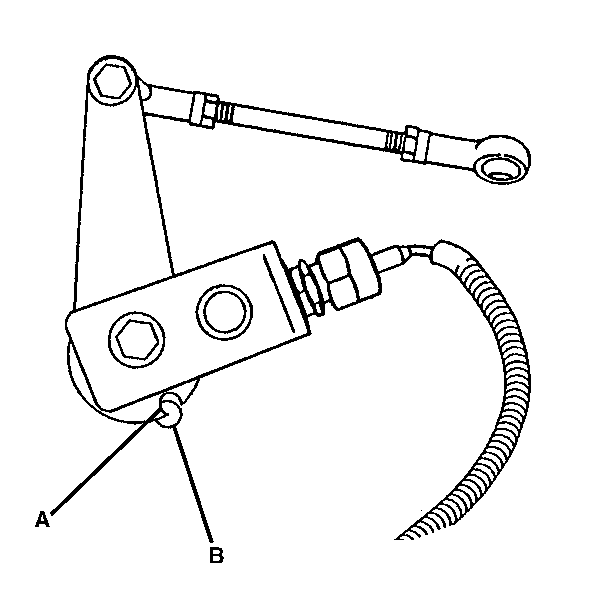
For 1990-2009 cars only
Removal Procedure
- Move the column shift lever to P (Park).
- Disconnect the connector from the end of the switch.
- Remove the jam nut from the threaded portion of the switch.
- Remove the switch from the bracket assembly.

Installation Procedure
- Install the switch into the bracket assembly.
- Install the jam nut. Do not secure the nut.
- Connect the connector.

Adjustment Procedure
- Insert a 3/8 inch drill bit through holes A and B.
- Adjust the switch so that the plunger makes contact with the clevis pin and the clevis pin makes contact with the cam assembly.
- Secure the jam nut and the lock washer securely to the bracket assembly.
- Remove the drill bit.
- Lubricate the clevis pin and the plunger face contact points with multi-purpose lubricant.
- With the ignition ON, move the shift lever from P (Park) and check the parking brake operation.
- Repeat the procedure if necessary.

If the drill bit does not slide through the aligning holes, refer to Hydraulic Auto Apply Control Rod Adjustment before continuing with this procedure.
Do not compress the plunger of the switch more than 0.5 mm (0.020 in) in this position.
