CAMPAIGN: REAR AXLE SHAFT MAY BREAK

MODELS: 1982 C,K25 AND P25 SERIES LIGHT DUTY TRUCKS EQUIPPED WITH 9 1/2" RING GEAR REAR AXLE
The National Traffic and Motor Vehicle Safety Act, as amended, provides that each vehicle which is subject to a recall campaign of this type must be adequately repaired within a reasonable time after the owner has tendered it for repair. A failure to adequately repair within 60 days after tender of a vehicle is prima facie evidence of failure to repair within a reasonable time.
If the condition is not adequately repaired within a reasonable time, the owner may be entitled to an identical or reasonably equivalent vehicle at no charge, or to a refund of the purchase price less a reasonable allowance for depreciation.
In order to avoid having to provide these burdensome solutions, every effort must be made to promptly schedule an appointment with each owner and to repair his vehicle as soon as possible. As you will see in reading the attached copy of the letter which is being sent to owners, the owner is being instructed to contact the nearest GMC Zone Office if his dealer does not remedy the condition within five days of the mutually agreed upon service date. If the condition is not remedied within a reasonable time, he is instructed on how to contact the National Highway Traffic Safety Administration.
DEFECT INVOLVED
General Motors has determined that a defect which relates to motor vehicle safety exists in the rear axle shafts installed in some 1982 C,K25 and P25 Series Light Duty Trucks equipped with a 9 1/2" ring gear rear axle.
The rear axle shafts in these may have been improperly heat treated. As a result, the shaft may break which could allow the tire and wheel assembly to separate from the vehicle. If this occurs while the vehicle is in motion, it could result in a loss of control and a vehicle crash could occur without prior warning.
VEHICLES INVOLVED
Involved are certain 1982 C,K25 and P25 Series Light Duty GMC Trucks equipped with a 9 1/2" ring gear rear axle and identified within the following vehicle breakpoints:
Plant From To ------ ----- -- Detroit C3502785 C3503512 Oshawa C1534281 C1538116 St. Louis CS523679 CS527363 Flint #1 CF712879 CF717000 Flint #2 CF520946 CF523641 Janesville CJ513844 CJ517110
The specific vehicles involved in this campaign have been identified by Vehicle Identification Number Computer Listings. These listings are furnished to all involved dealers with the campaign bulletin.
DEALER CAMPAIGN RESPONSIBILITY
Dealers are to service all vehicles subject to this campaign regardless of mileage, age of vehicle, or ownership from this time forward.
Whenever a vehicle subject to this campaign is taken into your new or used vehicle inventory or is in your dealership for service in the future, you should take the steps necessary to be sure the campaign correction has been made before reselling the vehicle.
On vehicles involved in this campaign that have been recently sold to a retail owner, where no owner's name and address were available to GMC Truck & Coach Division at the time of campaign initiation, the dealer will determine the owner's name and address from the dealership sales records. Please provide this information directly on the second copy of the listing next to the applicable VIN, so that our records may be updated and the appropriate notification mailed to the owner. This second copy should then be submitted to the address listed below in the previously supplied yellow campaign envelopes.
GMC Truck & Coach Division of General Motors Corporation 101 Union Street Plymouth, Michigan 48170
OWNER NOTIFICATION
Owners will be notified of this campaign on their vehicles by GMC Truck & Coach Division (see copy of Owner Letter included with this bulletin). A listing of owner names and addresses has been furnished to the involved dealers to enable dealers to follow up with owners involved in this campaign. This listing may contain owner names and addresses obtained from state motor vehicle registration records. The use of such motor vehicle registration data for any other purpose is a violation of law in several states. Accordingly, you are urged to limit the use of this listing to this campaign.
SERVICE PROCEDURES
Suspect Axle Assembly Identification - The only axle assemblies involved are those produced at Chevrolet Gear and Axle.
Dealers are to inspect all involved vehicles identified on the computer printout furnished to determine the source code, axle code and date code of the axle assembly. (Refer to Example)
LIGHT DUTY TRUCK REAR AXLE IDENTIFICATION
Example:
TKK 001 G 1 --- --- - - Axle & Date Code Source Code Shift Code
Vehicle Code Jan. 1 = 001 G = Gear & Axle 1st Shift
CODE IS STAMPED ON TOP OF RIGHT AXLE TUBE OUTBOARD OF CARRIER.
Axle assemblies with source code "G", and date code of 134 through 161 will require the replacement of both right and left rear axle shafts.
INSPECTION
1. Raise vehicle and locate the axle code which is stamped on top of right axle tube outboard of carrier. (Refer to example).
A. When the source code is "G" and the date code is lower than 134 or higher than 161, lower the vehicle, no further action is required, vehicle is not involved.
B. When the source code is "G" and the date code is 134 through 161, proceed with Correction and Installation Procedures.
REMOVAL PROCEDURE
1. Remove wheel and tire assemblies and brake drums.
2. Clean all dirt from around carrier cover.
3. Drain lubricant from carrier by removing cover.
4. Open Axles
a. Remove the differential pinion shaft lock screw and the differential pinion shaft.
b. Push flanged end of axle shafts toward center of vehicle and remove "C" locks from button end of shafts.
c. Remove axle shafts from housing, being careful not to damage oil seals.
Locking Axles
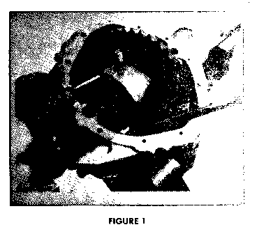
a. Rotate the case to the position shown in Figure No. 1. Support the pinion shaft so that it cannot fall into the case and then remove the differential pinion shaft lock screw.
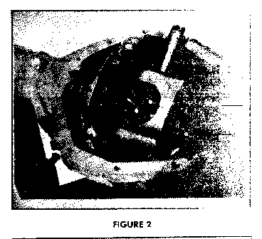
b. Carefully partially withdraw the differential pinion shaft as shown in Figure No. 2 and rotate the case until the shaft touches the housing.
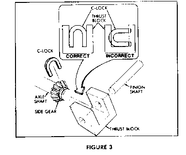
c. Reach into the case with a screwdriver or similar tool and rotate the "C" lock until its open end points directly inward as shown in Figure No. 3. The axle shaft cannot be pushed inward until the "C" lock is properly positioned. Do not force or hammer the axle shaft in an attempt to gain clearance.
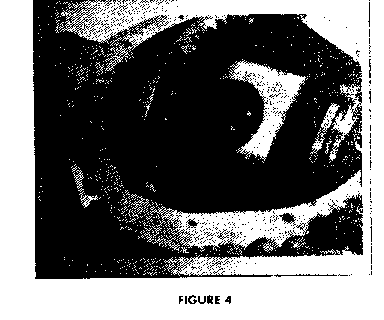
d. When the "C" lock is positioned to pass through the end of the thrust block, push the axle inward as shown in Figure No. 4 and remove the "C" lock.
e. Remove the axle shaft, being careful not to damage the oil seal and repeat Steps C through E for the opposite axle shaft.
When removing axle shafts, be sure the thrust washers in the differential case do not slide out.
INSTALLATION PROCEDURE
1. Utilizing a suitable arbor press, remove the bolts from the old axle shafts. Discard old shafts and reinstall bolts in new shaft, P/N 14035395.
2. Slide axle shafts into place. Be sure that splines on end of shaft do not damage oil seals and that they engage with splines of differential side gears.
3. Install axle shaft "C" locks on button end of axle shafts and push shafts outward so that "C" locks seat in counter bore of the differential side gears.
4. Position differential pinion shaft through pinion gears and case aligning hole in shaft with lock screw hole in the case. Install lock screw and torque to 20 ft. lbs.
5. Clean both the cover attaching surface of the carrier and cover of old RTV. Apply a 1/8" continuous bead of RTV, P/N 1052366, to the cover inboard of the bolt holes.
6. Position cover and secure in position torquing bolts to 20 ft lbs.
7. Fill axle with 5.5 pints of gear lubricant, P/N 1052271 (24 oz. container) or P/N 1052272 (15 gal. container). Do not use additive.
8. Install brake drums and wheel assemblies torquing wheel nuts to 100 ft. lbs.
9. Lower vehicle and test operation of axle.
PARTS INFORMATION
Parts required to complete this campaign are to be ordered by the dealer from the Warehousing and Distribution Division of General Motors (WDDGM).
Quantity Part Number Per Vehicle Description ----------- ----------- ------------ 14035395 2 Rear Axle Shaft
WARRANTY INFORMATION
Dealers should submit an accurately filled out Warranty Repair Order on each vehicle completed under this campaign.
Labor *Time Operation Allow- Allow- Trouble Number Description ance Code ------ ----------- ---- ---- V1330 Inspect rear axle 0.2 Hr. 96 assembly for source, axle and date codes. Codes not requiring axle shaft replacement as identified in this bulletin, indicate no further action required.
Labor *Time Operation Allow- Allow- Trouble Number Description ance Code ------ ----------- ---- ---- V1331 Inspect, replace 1.4 Hr. 96 both rear axle shafts (includes transfer of wheel bolts) when vehicle is within breakpoints with codes requiring axle shaft replace ment.
*For dealer to receive Administration Time Allowance associated with this campaign, add 0.1 hour to the Labor Operation Time Allowance.
CAMPAIGN IDENTIFICATION LABEL
Each vehicle modified in accordance with the instructions outlined in this product campaign bulletin will require a "Campaign Identification Label". Each label provides a space to include the five (5) digit Dealer Code of the dealer performing the campaign service. This information may be inserted with a typewriter or ballpoint pen.
Each "Campaign Identification Label" is to be located on the radiator core support in an area which will be visible when the vehicle is brought in for periodic servicing by the owner.
Apply "Campaign Identification Label" only on a clean dry surface.
ADMINISTRATIVE PROCEDURE
Procedures covering this campaign are outlined in Section V of your dealership's "GMC Truck Claims Processing Manual" issued October, 1981.
Dear GMC Truck Owner:
This notice is sent to you in accordance with the requirements of the National Traffic and Motor Vehicle Safety Act.
General Motors has determined that a defect which relates to motor vehicle safety exists in the rear axle shafts installed in some 1982 C,K25 and P25 Series Light Duty Trucks equipped with a 91/2" ring gear rear axle. The rear axle shafts in your vehicle may have been improperly heat treated. As a result, the shafts may break, which could allow the tire and wheel assembly to separate from the vehicle. If this occurs while the vehicle is in motion, it could result in a loss of control and a vehicle crash could occur without prior warning. As a precaution prior to having your vehicle inspected, you should avoid fast cornering, rapid accelerations, or any type of driving which may produce abnormally heavy loads on the rear axle shafts.
To prevent the possibility of this condition occurring on your vehicle, please contact your GMC Truck Dealer on or after the date shown below to arrange an appointment to have your vehicle inspected and if required, corrected. Correction involves the replacement of both rear axle shafts. The necessary service will be performed at no charge to you.
Instructions for making this inspection and/or correction have been sent to your GMC Truck Dealer. It is estimated that parts will be available to your dealer on August 31, 1982.
The labor time necessary to perform this correction ranges from approximately 15 minutes to inspect and one and a half hours to replace both rear axle shaft assemblies. Please allow additional time for the dealer to process your order.
If you take your vehicle to your dealer on the agreed service date and they do not remedy the condition without charge on that date, or within five days, you should contact your nearest GMC Truck Zone Office, either in person or by telephone, for assistance. The locations and telephone numbers of the Zone Offices are listed in your Owner's Manual. If your dealer or General Motors fails or is unable to remedy this condition without charge within a reasonable time, you may wish to notify the Administrator, National Highway Traffic Safety Administration, 400 Seventh Street, S.W., Washington, D. C. 20590.
The enclosed owner reply card identifies your vehicle. Presentation of this card to your dealer will assist him in making the necessary correction to your vehicle in the shortest possible time. If you have sold or traded your vehicle, please let us know by completing the postage paid owner reply card and returning it to us.
We are sorry to cause you this inconvenience; however, we have taken this action in the interest of your safety and continued satisfaction with our products.


General Motors bulletins are intended for use by professional technicians, not a "do-it-yourselfer". They are written to inform those technicians of conditions that may occur on some vehicles, or to provide information that could assist in the proper service of a vehicle. Properly trained technicians have the equipment, tools, safety instructions and know-how to do a job properly and safely. If a condition is described, do not assume that the bulletin applies to your vehicle, or that your vehicle will have that condition. See a General Motors dealer servicing your brand of General Motors vehicle for information on whether your vehicle may benefit from the information.
