LH LOWER CONTROL ARM CRACKING (INSTALL REINFORCEMENT KIT)

SUBJECT: LH LOWER CONTROL ARM CRACKING
MODELS: 1985-86 P3 COMMERCIAL MODEL TRUCKS WITH 350 GAS ENGINES (LT9) OR DIESEL ENGINES (LL4)
1985-86 G3 VANS WITHOUT RECREATION VEHICLE CHASSIS MODIFICATION (9A2) OR HEAVY DUTY FRONT SUSPENSION (F42)
1985-86 C3 MODEL TRUCKS BUILT WITHOUT HEAVY DUTY FRONT SUSPENSION (F42)
THIS BULLETIN CANCELS AND SUPERSEDES CAMPAIGN BULLETIN 86-C-19(D) ISSUED JANUARY 1992. ALL COPIES OF 86-C-19(D) SHOULD BE DESTROYED.
BULLETIN WAS REVISED TO ADD TWO LABOR OPERATIONS AND TO REVISE THE SERVICE PROCEDURE.
The National Traffic and Motor Vehicle Safety Act, as amended, provides that each vehicle which is subject to a recall campaign of this type must be adequately repaired within a reasonable time after the owner has tendered it for repair. A failure to adequately repair within 60 days after tender of a vehicle is prima facie evidence of failure to repair within a reasonable time.
If the condition is not adequately repaired within a reasonable time, the owner may be entitled to an identical or reasonably equivalent vehicle at no charge, or to a refund of the purchase price less a reasonable allowance for depreciation.
To avoid having to provide these burdensome solutions, every effort must be made to promptly schedule appointments with owners and to repair their vehicles as soon as possible. As you will see in reading the attached copy of the lefter which is being sent to owners, the owner is being instructed to contact the nearest GMC Zone Office if the dealer does not remedy the condition within five days of the mutually agreed upon service date. If the condition is not remedied within a reasonable time, they are instructed how to contact the National Highway Traffic Safety Administration.
DEFECT INVOLVED
General Motors has determined that a defect which relates to motor vehicle safety exists in certain 1985-86 P3 Commercial Model Trucks with 350 gas engines or 6.2L diesel engines, 1985-86 G3 Vans with 350 gas engines or 6.2L diesel engines and 1985-86 C3 Model trucks built without heavy duty front suspension. The left hand lower control arm can crack starting at the rear flange and progress to the ball joint mounting hole and eventually cause the lower ball joint to separate from the control arm. If this happens, a loss of vehicle steering control can occur which could result in a vehicle crash without prior warning.
To prevent this condition from occurring, dealers are to install a reinforcement brace to the left hand lower control arm.
VEHICLES INVOLVED
Involved are certain 1985-86 P3 Commercial Model Trucks with 350 gas engines (LT9) or 6.2L diesel engines (LL4), 1985-86 G3 Vans with 350 gas engines (LT9) or 6.2L diesel engines (LL4) and 1985-86 C3 Model trucks built without heavy duty front suspension (F42) built within the following VIN breakpoints:
Model Year Assembly Model Plant From Through ---------- -------------- ----- ---- ------- 1985 P3 Detroit F3500001 F3510494 C3 (without F42) Pontiac SOP EOP C3 (without F42) Ohsawa SOP EOP C3 (without F42) Janesville SOP EOP C3 (without F42) St. Louis SOP EOP G31303 Scarborough SOP EOP G31305 Scarborough/Lordstown SOP EOP G31306 Scarborough/Lordstown SOP EOP G31603 (without F42) Scarborough SOP EOP G31332 Scarborough SOP EOP G31632 (without 9A2) Scarborough SOP EOP 1986 P3 Detroit G3500001 G3504509 C3 (without F42) Janesville SOP EOP C3 (without F42) St. Louis SOP EOP G31303 Scarborough SOP EOP G31305 Scarborough/Lordstown SOP EOP G31306 Scarborough/Lordstown SOP EOP G31603 (without F42) Scarborough SOP EOP G31332 Scarborough SOP EOP G31632 (without 9A2) Scarborough SOP EOP
Vehicle Identification Number Computer Listings were previously furnished to all involved dealers with the original campaign bulletin.
DEALER CAMPAIGN RESPONSIBILITY
All unsold new vehicles in dealers' possession and subject to this campaign MUST be held and inspected/repaired per the service procedure of this campaign bulletin BEFORE owners take possession of these vehicles.
Dealers are to service all vehicles subject to this campaign at no charge to owners, regardless of mileage, age of vehicle, or ownership, from this time forward.
Owners of vehicles recently sold from your new vehicle inventory are to be contacted by the dealer, and arrangements made to make the required cor- rection according to instructions contained in this bulletin.
In summary, whenever a vehicle subject to this campaign enters your vehicle inventory, or is in your dealership for service in the future, please take the steps necessary to be sure the campaign correction has been made before selling or releasing the vehicle.
If the name and address of the owner of an involved vehicle was unavailable to GMC Truck Division at the time of campaign initiation, the dealer must determine the owner's name and address from the dealership sales records. Please provide this information directly on the second copy of the listing next to the applicable VIN so that our records may be updated and the appropriate notification mailed to the owner. This second copy should then be submitted to the address listed below in the previously supplied yellow campaign envelopes.
GMC Truck Division General Motors Corporation 101 Union Street Plymouth, Michigan 48170
OWNER NOTIFICATION
Owners of vehicles involved were notified of this campaign by GMC Truck Division (see copy of owner lefter included with this bulletin). A listing of owner names and addresses was previously furnished to the involved dealers to enable dealers to follow up with owners involved in this campaign. The listing may contain owner names and addresses obtained from State Motor Vehicle Registration records. The use of such motor vehicle registration data for any other purpose is a violation of law in several states. Accordingly, you are urged to limit the use of the listing to this campaign.
SERVICE PROCEDURE
INSTRUCTIONS FOR INSTALLATION OF THE REINFORCEMENT KIT
NOTE: Disregard instructions enclosed in kit #15624685. Use procedures "Initial Position of Reinforcement" and "Reinforcement Installation" listed below.
PRELIMINARY INSPECTION OF THE CONTROL ARM
1. Raise the left front of the vehicle and support it with suitable safety stands.
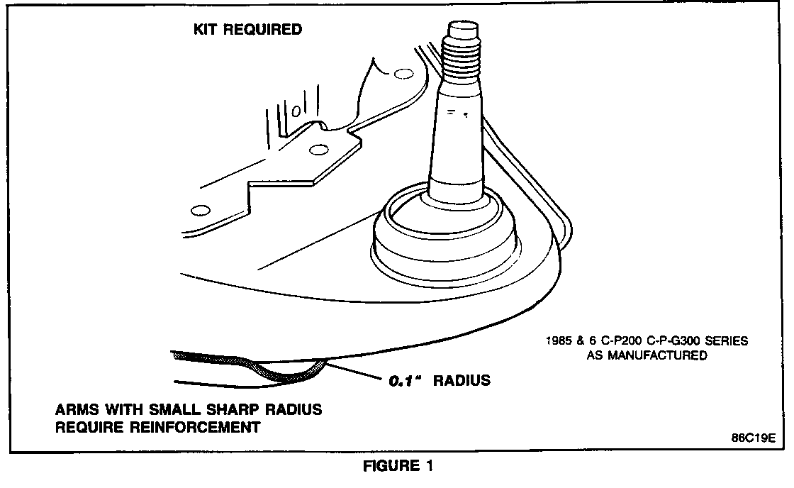
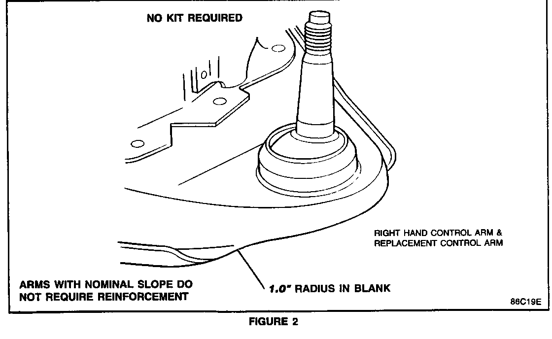
2. Inspect the left hand lower control arm to determine if the subject vehicle requires modification. Arms subject to kit installation will have a small radius of 0.1 inch (2.54 mm) at the flange-to-nose transition (Figure 1), instead of the intended 1.0 inch (25.4 mm) nominal radius (Figure 2). All right hand lower control arms have the proper radius and may be used for comparison.
NOTICE: Some 85186 vehicles may have had their lower control arms replaced. If inspection of the left lower control arm indicates the 1.0 inch (25.4 mm) nominal radius shown in Figure 2, the control arm will NOT require a reinforcement kit. Submit a Product Campaign claim for INSPECT CONTROL ARM no action required.
INITIAL POSITIONING OF THE REINFORCEMENT
1. Clean the left hand lower control arm of all dirt, rust, grease, and undercoating from the spring pocket outboard. Clean both the top and bottom areas of the control arm. This will insure good mechanical contact of the reinforcement and U-bolt to the control arm and ball joint flange. Use appropriate solvents and/or a wire brush as required.
NOTICE: If the control arm and the reinforcement are not thoroughly cleaned, the U-bolt may "walk" off the bottom of the ball joint when it is tightened.
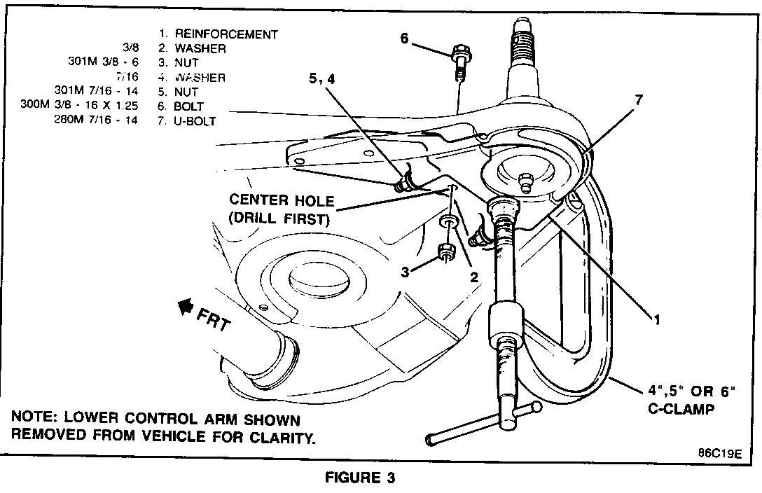
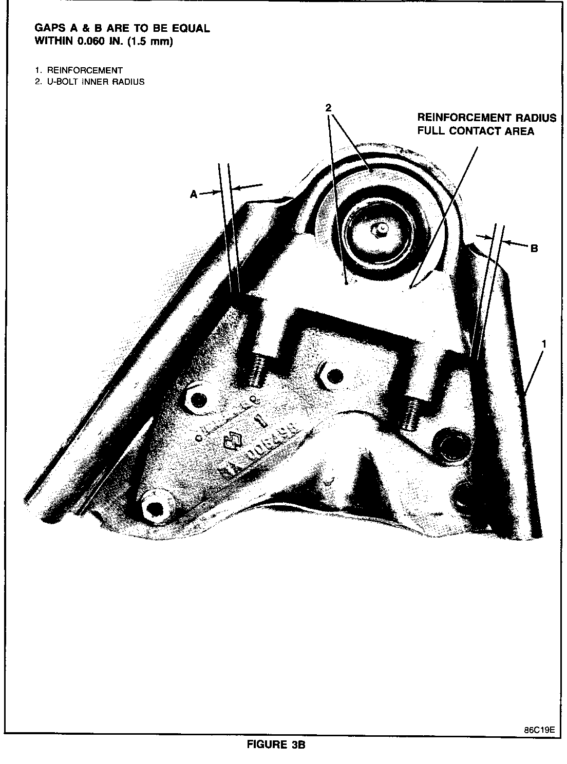
2. Center the reinforcement (Figure 3B "1") between the flanges. Gaps A & B (Figure 3B) are to be equal within 0.060 inch (1.5 mm). Secure the reinforcement with a "C" clamp.
Important
The reinforcement is installed CORRECTLY when the ball joint makes full contact with the reinforcement radius (Figure 3B), not just in the center section of the reinforcement.
The reinforcement is designed to fit ball joints with a bottom diameter of 2.60 inches (66 mm) or greater. The technician may find that the ball joint does not make full contact with the radius of the reinforcement when the reinforcement is centered between the flanges (Step 2 "INITIAL POSITIONING OF REINFORCEMENT").
It is possible that an aftermarket ball joint with a bottom diameter which is less than 2.60 inches (66 mm) has been installed. This does not allow for full contact with the radius of the reinforcement. When this happens, only a small section of the ball joint will be centered on the reinforcement. If this occurs, make certain the ball joint is clean as described in step 1. Then measure the bottom diameter of the ball joint with calipers. If the measurement is LESS THAN 2.6 inches (66 mm), the ball joint must be replaced with a Genuine GM ball joint.
3. Install the U-bolt (Figure 3, "7") and torque it to approximately 10 N-m (7 lbs. ft.).
Important
THIS STEP MUST BE PERFORMED BEFORE PROCEEDING TO STEP 4.
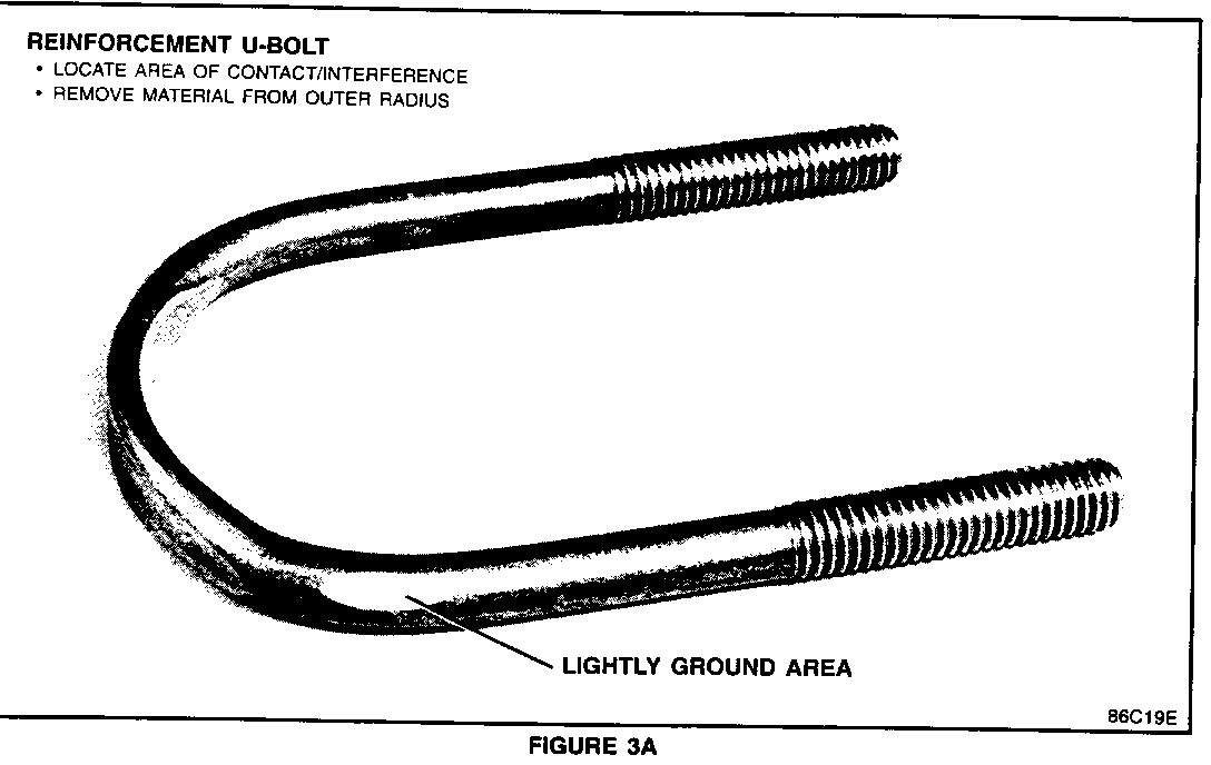
NOTICE: When correctly installed, the U-bolt, will be about even with bottom of the ball joint. The U-bolt is NOT designed to fit into the galley of the control arm. On some vehicles the U-bolt may contact the flange edge of the control arm and interfere with the correct installation. In these cases you may remove only enough material (LIGHTLY grind) (Figure 3A) from the outer radius of the U-bolt to allow clearance between the U-bolt and the control arm (Figure 3, "7") .
4. Drill a center hole with a 3/8 inch (9.5 mm) drill. The reinforcement (Figure 3, "1") has been designed to be used as a drill guide. When drilling, keep the drill as perpendicular as possible.
5. Install a 3/8-16 bolt (Figure 3, "6"), nut (Figure 3, "3") and washer (Figure 3, "2") in the center hole and torque them to approximately 18 N-m (1 3 lbs. ft).
6. Remove the "C" clamp.
7. Drill the three remaining holes in any sequence.
8. Disassemble the reinforcement (Figure 3, "1") and U-bolt (Figure 3, "7") from the control arm and remove all of the chips or burrs from the reinforcement.
INSTALLATION OF THE REINFORCEMENT
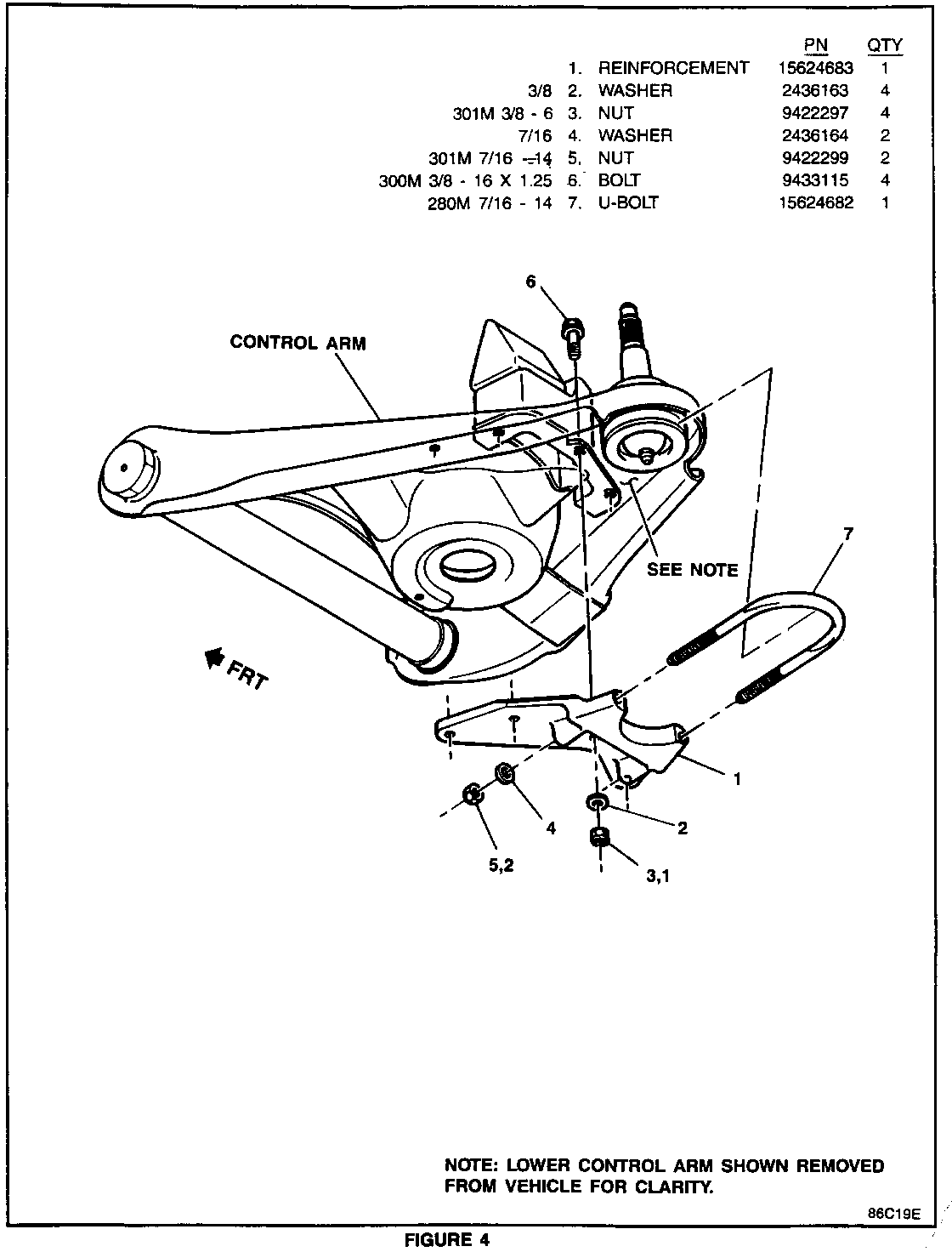
1. Reinstall the reinforcement (Figure 4, "1") and U-bolt (Figure 4, "7"). Hand start all of the bolts. Tighten the U-bolt nuts (Figure 4, "5") to approximately 22 N.m. (16 lbs. ft.). Make sure the U-bolt is ALIGNED with the bottom edge of the ball joint and is NOT COCKED while continuing to torque.
NOTICE: If the rear most bolt head flange interferes with the bump stop bracket, install the bolt from the bottom of the control arm.
2. Torque the 3/8-16 bolts (Figure 4, "6") to 37 - 43 N.m. (27 - 32 lbs. ft.). Tighten the center bolt first and the remainder in any sequence.
3. Torque the U-bolt nuts (Figure 4, "5") to 40 - 46 N.m. (30 - 34 lbs. ft.).
4. Lower the vehicle.
5. Install "Campaign Identification Label."
PARTS INFORMATION
Parts are to be obtained from General Motors Service Parts Operation (GMSPO). To ensure that these parts will be obtained as soon as possible, they should be ordered from GMSPO on a C.I.O. order with no special instruction code but order under an advise code (2).
Part Number Description Quantity ------ ----------- -------- 15624685 Kit, lower control arm 1 reinforcement
9766424 Ball Joint As Required
NOTE: Disregard instructions enclosed in kit #15624685. Use procedures "Initial Position of Reinforcement" and "Reinforcement Installation" listed above.
WARRANTY INFORMATION
Dealers should submit an accurately filled out Warranty Repair Order on each vehicle completed under this campaign.
Labor Operation *Time Trouble Number Description Allowance Code --------- ----------- --------- ------- V4773 Inspect Lower Con- 0.2 Hr. 96 trol Arm (No Action Required)
V4774 Install Reinforce- 0.7 Hr. 96 ment Kit & Mea- sure Ball Joint
V4775 Install Ball Joint 1.2 Hr. 96 and Install Rein- forcement Kit
* For dealer to receive Administrative Time Allowance associated with this campaign, add 0.1 hour to the Labor Operation Time Allowance.
CAMPAIGN IDENTIFICATION LABEL
Each vehicle corrected in accordance with the instructions outlined in this product campaign bulletin will require a "Campaign Identification Label". Each label provides a space to include the campaign number and five (5) digit dealer code of the dealer performing the campaign service. This information may be inserted with a typewriter or ball point pen.
Each "Campaign Identification Label" is to be located on the radiator core support in an area which will be visible when the vehicle is brought in for periodic servicing by the owner.
Apply "Campaign Identification Label" only on a clean, dry surface.
ADMINISTRATIVE PROCEDURE
Procedures covering this campaign are outlined in Section V of your dealership's "GM Truck Claims Processing Manual" #P9119.
Dear GMC Truck Owner:
This notice is sent to you in accordance with the requirements of the National Traffic and Motor Vehicle Safety Act.
General Motors has determined that a defect which relates to motor vehicle safety exists in certain 1985-86 P3 Commercial Model Trucks with 350 gas engines or 6.2L diesel engines, 1985-86 G3 Vans with 350 gas engines or 6.2L diesel engines and 1985-86 C3 Model trucks built without heavy duty front suspension. The left hand lower control arm can crack starting at the rear flange and progress to the ball joint mounting hole and eventually cause the lower ball joint to separate from the control arm. If this happens, a loss of vehicle steering control can occur which could result in a vehicle crash without prior warning.
To prevent this condition from occurring, dealers are to install a reinforcement brace to the left hand lower control arm. This service will be completed for you at no charge.
Instructions for performing this service have been sent to your GMC Truck dealer. Please contact your dealer to arrange a service date. The labor time necessary to perform this correction will be approximately one hour. Please ask your dealer how much additional time will be needed to process your vehicle.
Your GMC Truck dealer is best equipped to provide service to ensure your vehicle is corrected as promptly as possible. However, if you take your vehicle to your dealer on the agreed service date and they do not service this condition on that date or within five days, we recommend you contact your nearest GMC Truck Zone Office by telephone. The Zone Office will assist you and your dealer in getting your vehicle corrected. The telephone numbers of the Zone Offices are listed in your Warranty and Owner Assistance Information Manual.
After contacting your dealer and the Zone Office, if you are still not satisfied that we have done our best to remedy this condition without charge within a reasonable time, you may wish to write the Administrator, National Highway Traffic Safety Administration, 400 Seventh Street, S.W., Wash- ington, D.C. 20590, or call 800-424-9393 (Washington, D.C. residents use 366-0123).
The enclosed postage paid owner reply card identifies your vehicle. Presentation of this card to your dealer will assist in making the necessary correction to your vehicle in the shortest possible time. If you have sold or traded your vehicle, please furnish us complete name and address of the person you sold or traded your vehicle to and retum the card to us.
We are sorry to cause you this inconvenience; however, we have taken this action in the interest of your safety and continued satisfaction with our product.
General Motors bulletins are intended for use by professional technicians, not a "do-it-yourselfer". They are written to inform those technicians of conditions that may occur on some vehicles, or to provide information that could assist in the proper service of a vehicle. Properly trained technicians have the equipment, tools, safety instructions and know-how to do a job properly and safely. If a condition is described, do not assume that the bulletin applies to your vehicle, or that your vehicle will have that condition. See a General Motors dealer servicing your brand of General Motors vehicle for information on whether your vehicle may benefit from the information.
