CAMPAIGN: STEERING COLUMN INSTALLATION

Models: 1989 P3 Trucks With I-Beam Front Axle (FS3) and Automatic Transmission (M40)
General Motors of Canada has determined that a defect which relates to motor vehicle safety exists in certain 1989 P3 commercial truck chassis equipped with I-beam front axles (RPO FS3) and automatic transmissions (RPO M40). The shift lever may not drop into the "Park" detent when placed into the "Park" position. In this position, it is possible for the shift lever to move from "Park" to "Reverse" without having to lift the shift lever. This inability of the shift lever to go into the "Park" detent could allow unexpected vehicle movement and a vehicle crash could occur.
To correct this condition, it will be necessary to inspect for clearance between the shift rod lever and dash panel opening, and if necessary, adjust the steering column and shift linkage to obtain clearance. If clearance is unobtainable by adjustment alone, then the upper steering column bracket will be replaced.
VEHICLES INVOLVED:
Involved are certain 1989 Chevrolet and GMC P3 trucks built within the following VIN breakpoints:
MODEL/YEAR PLANT FROM THROUGH ---------- ----- ---- -------- P3 1989 Chev Detroit K3300002 K3310786
P3 1989 GMC Detroit K3500020 K3501191
All affected vehicles have been identified by the VIN listing provided to involved dealers with this bulletin. Any dealer not receiving a listing was not shipped any of the affected vehicles.
DEALER CAMPAIGN RESPONSIBILITY:
Dealers are to service all vehicles subject to this campaign at no charge to owners, regardless of mileage, age of vehicle, or ownership, from this time forward.
Whenever a vehicle subject to this campaign is taken into your new or used vehicle inventory, or it is in your dealership for service in the future, you should take the steps necessary to be sure the campaign correction has been made before reselling or releasing the vehicle.
Owners of vehicles recently sold from your new vehicle inventory are to be contacted by the dealer, and arrangements made to make the required modification according to instructions contained in this bulletin.
CAMPAIGN PROCEDURE:
Refer to Section 4 of the Service Policies and Procedures Manual for the detailed procedure on handling Product Campaigns. Dealers are requested to complete the campaign on all transfers as soon as possible.
OWNER NOTIFICATION:
All owners of record at the time of campaign release are shown on the attached computer listing and have been notified by first class mail from General Motors. The listings provided are for campaign activity only and should not be used for any other purpose.
PARTS INFORMATION:
Parts required to complete this campaign should be ordered through regular channels, as follows:
Part Number Description Quantity/Vehicle ----------- ------------ ----------------- 15594610 Bracket Assembly 1
PARTS AND LABOUR CLAIM INFORMATION:
Credit for the campaign work performed will be paid upon receipt of a properly completed campaign claim card, RAPID terminal or DCS transmission in accordance with the following:
Repair Code Description Time Allowance ----------- ----------- -------------- 1A Inspect, no action necessary .3
2A Inspect, adjust steering column .6
3A Inspect, adjust column and .7 shift linkage
4A Inspect, replace bracket adjust .8 column and linkage
Time allowance includes 0.1 hour for dealer administrative detail associated with this campaign. Parts credit will be based on dealer net plus 30% to cover parts handling.
SERVICE PROCEDURE:
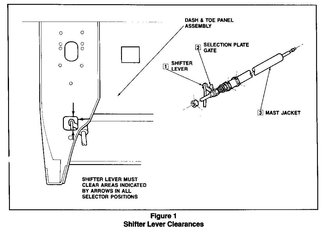
A. INSPECTION PROCEDURE (See Figure 1)
1. Set parking brake and block wheels.
2. Place transmission shift selector in "PARK" position.
CAUTION:
With the selector lever in the "PARK" position, check to insure that the parking pawl is engaged and that the vehicle will not roll and cause personal injury.
3. Raise hood and check lower shift lever (1) at base of mast jacket (3) for proper seating in selector gate plate (2). Also, check for any interference between shift lever (1) and clearance hole in dash panel. If there is clearance, no further action will be required.
4. If lever (1) does not seat properly in the selector gate plate (2) or there is any interference at clearance hole when shifting through gear positions, the mast jacket must be readjusted as described below.
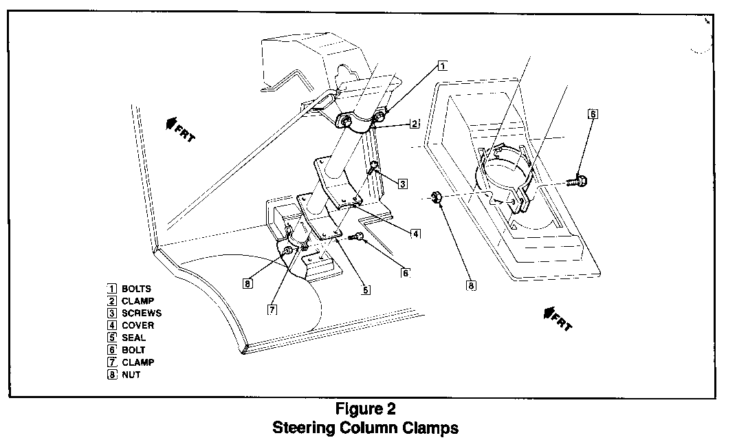
B. STEERING COLUMN ADJUSTMENT PROCEDURE (See F
1. Loosen upper mast jacket clamp (2) on brake hanger bracket.
2. Lift floor mat and remove 4 screws (3 ) on mast jacket floor cover (4). Lift cover (4) and seal (5) up out of the way on jacket.
3. Loosen lower mast jacket clamp (7).
4. Place shift selector in "PARK" position.
5. Move mast jacket up or down until lower shift lever (1 Figure 1) is approximately halfway between top and bottom of clearance hole in dash panel and proper clearance is obtained.
6. Turn mast jacket clockwise or counterclockwise until clearance is obtained between lower shift lever (1) and side of clearance hole in dash panel.
7. Tighten bolts (1) on upper clamp and bolts (8) on lower clamp (7). Torque all bolts to 14-17 N.m (125-150 lb. in.)
8. Move shift selector out of "PARK" position and then return to "PARK" position. Visually check lower lever for proper clearance in dash panel clearance hole in all gear positions and full seating in park position of selector lever plate gate (2).
NOTE: If shift selector still cannot be properly positioned, it will be necessary to adjust the shift linkage as described in Procedure C below.
The engine must start in the "P" (park) or "N" (neutral) positions only. Adjust neutral start switch if needed.
CAUTION:
With the selector lever in the "PARK" position, check to insure that the parking pawl is engaged and that the vehicle will not roll and cause personal injury.
9. Replace mast jacket floor cover (4) and seal (5) and secure with (4) screws.
10. Replace floor mat.
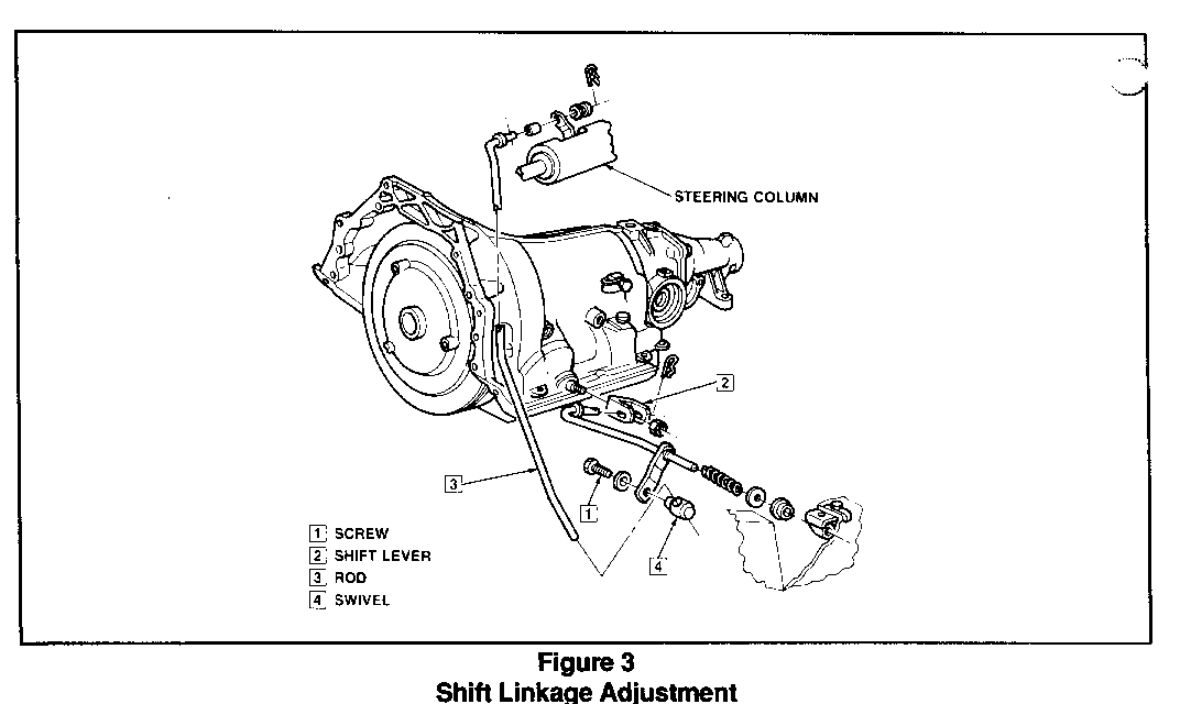
C. SHIFT LINKAGE ADJUSTMENT PROCEDURE (Figure 3)
1. Apply parking brake and block wheels.
2. Loosen swivel screw (1).
3. Put column selector lever in the "N" (neutral) position.
NOTE: Be sure to put column selector lever into the neutral gate, do NOT use the indicator to find the neutral position.
4. Put the transmission in neutral by moving the shift lever (2) counterclockwise (as you face the transmission) to the forward position (the transmission will be in "Park"), and then back to the second detent.
5. Hold the rod (3) tightly in the swivel (4) and tighten the screw to 23 N.m (17 ft. lb.).
6. Put the column selector lever in the "P" (park) position.
7. Check the adjustment as follows:
a. The column selector must go into all positions.
b. The engine must start in the "P" (park) or "N" (neutral) position only. Adjust neutral start switch is needed.
CAUTION:
With the selector lever in the "PARK" position, check to insure that the parking pawl is engaged and the vehicle will not roll and cause personal injury.
8. If proper adjustment cannot be accomplished, the steering column upper bracket assembly may be out of tolerance. Replace the bracket assembly and repeat steering column and linkage adjustment procedures. (It is estimated that very few vehicles will require bracket replacement.)
9. Release parking brake and remove wheel blocks. Install campaign identification label.
INSTALLATION OF CAMPAIGN IDENTIFICATION LABEL
Clean surface of radiator upper mounting panel and apply a Campaign Identification Label. Make sure the correct campaign number is inserted on the label. This will indicate that the campaign has been completed.
General Motors of Canada has determined that a defect which relates to motor vehicle safety exists in certain 1989 P3 commercial truck chassis equipped with optional I-beam front axles (RPO FS3) and automatic transmissions (RPO M40). The shift lever may not drop into the "Park" detent when placed into the "Park" position. In this position, it is possible for the shift lever to move from "Park" to "Reverse" without having to lift the shift lever. This inability of the shift lever to go into the "Park" detent could allow unexpected vehicle movement and a vehicle crash could occur.
Owners/Drivers should continue following the "Parking/Leaving Drivers Seat" instructions as stated in the Owners Manual prior to existing the vehicle, which includes applying the parking brake.
To correct this condition, it will be necessary to inspect for clearance between the shift rod lever and dash panel opening, and if necessary, adjusting the steering column and shift linkage to obtain clearance. If clearance is unobtainable by adjustment alone, then the upper steering column bracket will be replaced. This service will be performed for you at no charge.
Please contact your GM dealer as soon as possible to arrange a service date. Instructions for making this correction have been sent to your dealer. Please ask your dealer if you wish to know how much additional time will be needed to schedule and process your vehicle. The labour time necessary to perform this service (inspection/correction) is approximately fifteen (15) to forty-five (45) minutes.
This letter identifies your vehicle. Presentation of this letter to your dealer will assist their Service personnel in completing the necessary correction to your vehicle in the shortest possible time.
Further assistance, if required, may be obtained from the General Motors Zone Office nearest you. Your vehicle Owner's Manual provides the location and phone number of each respective Zone Office.
We are sorry to cause yoy this inconvenience; however, we have taken this action in the interest of your continued satisfaction with our products.


General Motors bulletins are intended for use by professional technicians, not a "do-it-yourselfer". They are written to inform those technicians of conditions that may occur on some vehicles, or to provide information that could assist in the proper service of a vehicle. Properly trained technicians have the equipment, tools, safety instructions and know-how to do a job properly and safely. If a condition is described, do not assume that the bulletin applies to your vehicle, or that your vehicle will have that condition. See a General Motors dealer servicing your brand of General Motors vehicle for information on whether your vehicle may benefit from the information.
