CAMPAIGN: DANA REAR AXLE BEARING RETAINER/END PLAY

Subject: PRODUCT SAFETY CAMPAIGN 91C20 DANA REAR AXLE BEARING RETAINER/END PLAY
Model and Year: 1990-91 P30 MOTORHOME CHASSIS WITH DANA MODEL 80 REAR AXLE
TO: ALL CHEVROLET DEALERS
The National Traffic and Motor Vehicle Safety Act, as amended, provides that each vehicle which is subject to a recall campaign of this type must be adequately repaired within a reasonable time after the owner has tendered it for repair. A failure to repair within sixty (60) days after tender of a vehicle is prima facie evidence of failure to repair within a reasonable time.
If the condition is not adequately repaired within a reasonable time, the owner may be entitled to an identical or reasonably equivalent vehicle at no charge or to a refund of the purchase price less a reasonable allowance for depreciation.
To avoid having to provide these burdensome solutions, every effort must be made to promptly schedule an appointment with each owner and to repair their vehicle as soon as possible. As you will see in reading the attached copy of the letter that is being sent to owners, the owners are being instructed to contact the GMC Truck Customer Assistance Center if their dealer does not remedy the condition within five (5) days of the mutually agreed upon service date. If the condition is not remedied within a reasonable time, they are instructed on how to contact the National Highway Traffic Safety Administration.
DEFECT INVOLVED
General Motors has determined that certain 1990-91 GMC Truck P30 Motorhome Chassis fail to conform to the requirements of Federal Motor Vehicle Safety Standard (FMVSS) 105, "Hydraulic Brake Systems". These vehicles, equipped with 4.63 ratio Dana model 80 rear axles, heavy duty chassis, and 4-wheel disc brakes may have a missing rear axle outer bearing retaining ring and/or greater than specified bearing end play. Either of these conditions will allow the wheel rotor and hub assembly to shift relative to the spindle. This movement can cause the brake caliper piston to recede farther than normal into the piston bore which would require greater than normal brake fluid displacement when the service brakes are applied. Should this occur at a time when minimum stopping distance is required, it could result in a vehicle crash, without warning.
To correct this condition, involved vehicles will have both rear axle hubs inspected for the condition(s) and corrected if necessary.
VEHICLES INVOLVED
Involved are certain 1990-91 GMC Truck P30 Motorhome Chassis vehicles built within the following VIN breakpoints:
YEAR PLANT FROM THROUGH ----- ------- -------- -------- 1990 Detroit L35-2333 L3503447
Involved vehicles have been identified by Vehicle Identification Number Computer Listings. Computer listings contain the complete Vehicle Identification Number, owner name and address data, and are furnished to involved dealers with the campaign bulletin. Owner name and address data furnished will enable dealers to follow-up with owners involved in this campaign.
These listings may contain owner names and addresses obtained from State Motor Vehicle Registration Records. The use of such motor vehicle registration data for any other purpose is a violation of law in several states. Accordingly, you are urged to limit the use of this listing to the follow-up necessary to complete this campaign. Any dealer not receiving a computer listing with the campaign bulletin has no involved vehicles currently assigned.
OWNER NOTIFICATION
Owners will be notified of this campaign on their vehicles by GMC Truck Motor Division (see copy of owner letter included with this bulletin).
DEALER CAMPAIGN RESPONSIBILITY
Dealers are to service all vehicles subject to this campaign at no charge to owners, regardless of mileage, age of vehicle, or ownership, from this time forward.
Whenever a vehicle subject to this campaign is taken into your new or used vehicle inventory, or it is in your dealership for service in the future, you should take the steps necessary to be sure the campaign correction has been made before reselling or releasing the vehicle.
Owners of vehicles recently sold from your new vehicle inventory are to be contacted by the dealer, and arrangements made to make the required correction according to instructions contained in this bulletin.
This bulletin is notice to you that the new motor vehicles included in this campaign may not comply with the standard identified above. Under Section 108 of the National Traffic and Motor Vehicle Safety Act, it is illegal for a dealer to sell a new motor vehicle which the dealer knows does not comply with an applicable Federal Motor Vehicle Safety Standard. As a consequence, if you sell any of these motor vehicles without first performing the campaign correction, your dealership may be subject to a civil penalty up to $1,000 for each such sale.
PARTS INFORMATION
Parts required to complete this campaign are to be obtained from General Motors Service Parts Operations (GMSPO). To ensure these parts will be obtained as soon as possible, they should be ordered from GMSPO on a "C.I.O." order with no special instruction code, but on an advise code (2).
Quantity/ Part Number Description Vehicle ----------- ----------------- ---------- 00473636 Round Nut 4 00473629 Lock Hub Nut 2 473628 Washer 2 09412405 Outer Bearing Assembly 2 00594324 Retaining Ring 2 09412426 Inner Bearing Assembly 2 15589475 Wheel Seal 2 03685199 Rear Axle Cap Gasket 2
SERVICE PROCEDURE: Figures for these procedures are found on pages 6 through 9.
FOR ALL VEHICLES: PERFORM BOTH INSPECTION PROCEDURES A AND B. THEN, BASED ON RESULTS OF PROCEDURE B, PERFORM EITHER PROCEDURE C OR PROCEDURE D TO COMPLETE CAMPAIGN REQUIREMENTS.
A. BEARING END PLAY INSPECTION PROCEDURE
Tools Required: J 8001 Dial Indicator Set J 23409 Dial Indicator Extension Set J 26900-13 Magnetic Base
1. Block front wheels and raise vehicle until rear wheels are free to rotate.
2. Check wheel bearing play by grasping tire at top and pulling and pushing back and forth, or by using a pry bar under tire. If tapered roller bearings are properly adjusted, movement of brake disc in relation to brake flange plate will be barely noticeable and the wheel will turn freely. If movement is excessive then the bearings are out of adjustment and possibly damaged. Using dial indicator (J 8001), magnet base (J 26900-13) and extension arm set (J 23409) verify any apparently excessive bearing end play by setting dial indicator on axle tube and set roller end to rotor of hub. If, when pulling hub outward, movement is within .001 to .010 inch, end play is acceptable. End play in excess of .010 inch is unacceptable and should be repaired.
NOTICE: Make sure brakes are fully released and do not drag when checking for wheel bearing play.
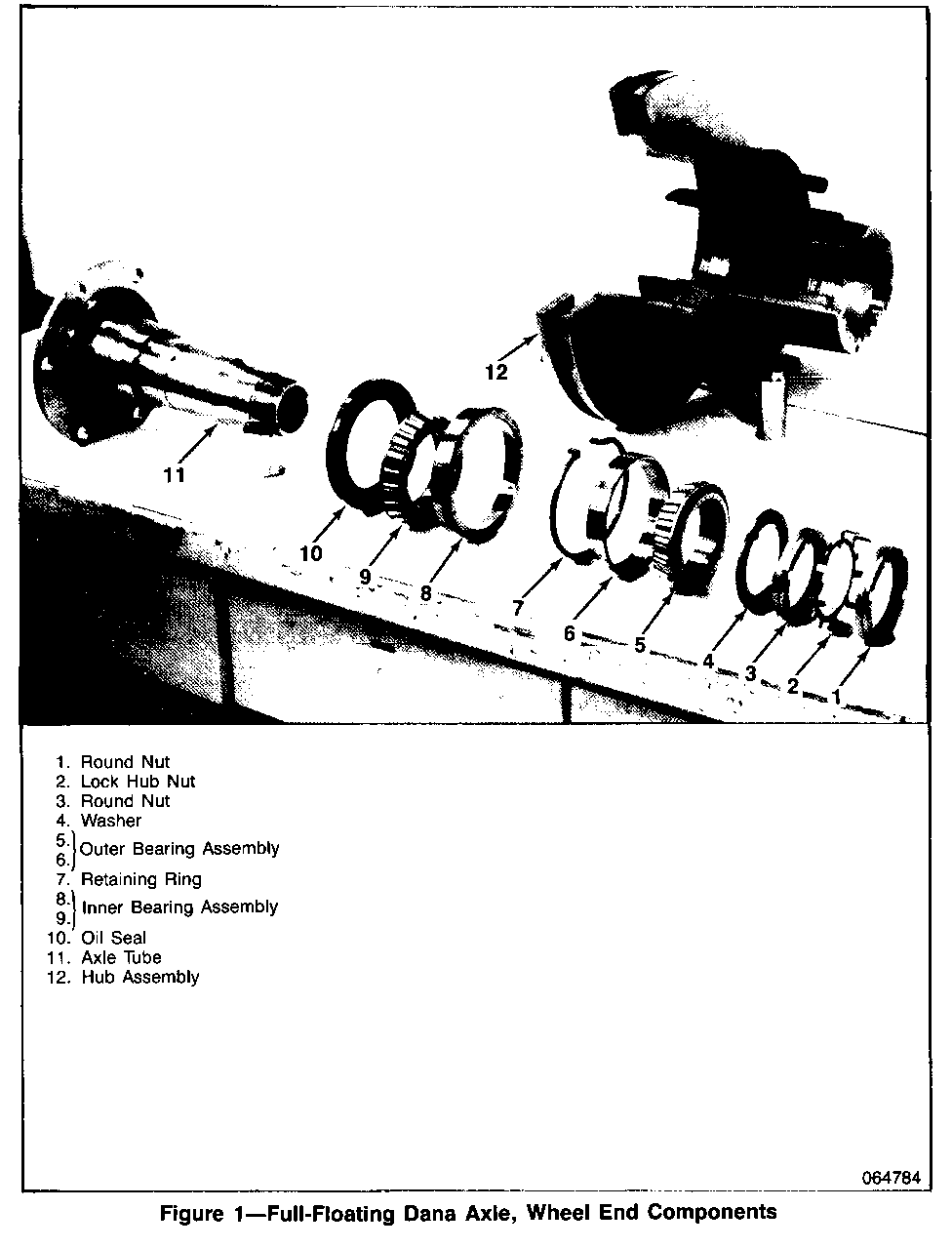
3. If excessive bearing end play is detected, include replacement of inner and outer bearings and oil seal (Fig. 5 and 9) and oil seal (10) as illustrated in figure 1, according to Procedure C (Retaining Ring Is Not Missing) or D (Retaining Ring Is Missing), whichever is necessary. Also, check axle shaft for any damage that may have occurred from axle shaft contact with inner side of axle tube (Fig. 1, 11). Replace as necessary.
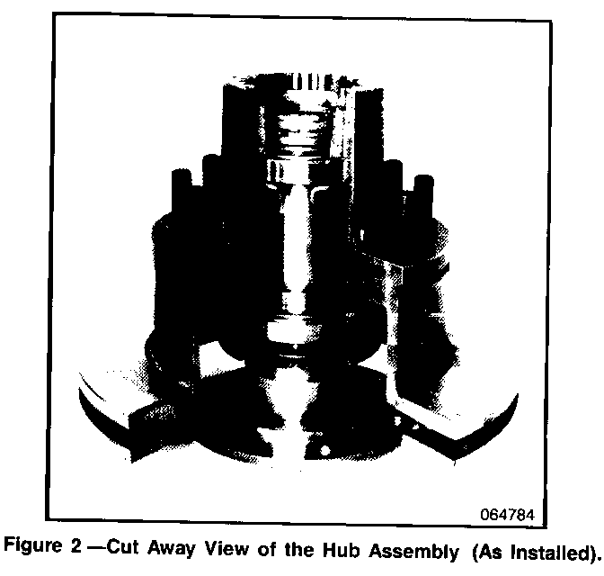
B. RETAINING RING INSPECTION PROCEDURE (Ref. Figures 1 and 2)
Tool Required: J 2222 C Wheel Bearing Nut Wrench
NOTICE: When fasteners are removed, always reinstall them at the same location from which they were removed. If a fastener needs to be replaced, use correct part number for application. If correct part number fastener is not available, a fastener of equal size and strength (or stronger) may be used. Fasteners that are not reused and those requiring thread locking compound will be called out in this procedure. Correct torque value must be used when installing fasteners that require torque. If above conditions are not followed, parts or systems damage could result.
1. Block front wheels and raise vehicle until wheel is free to rotate. Remove wheel and tire assembly.
2. Disconnect and suspend caliper. Refer to Section 5A2 of 1990 Service Manual. Inspect brake linings and caliper rotor for possible cracks or damage.
NOTICE: Do not allow brake components to hang from flexible hoses as damage to hoses may occur.
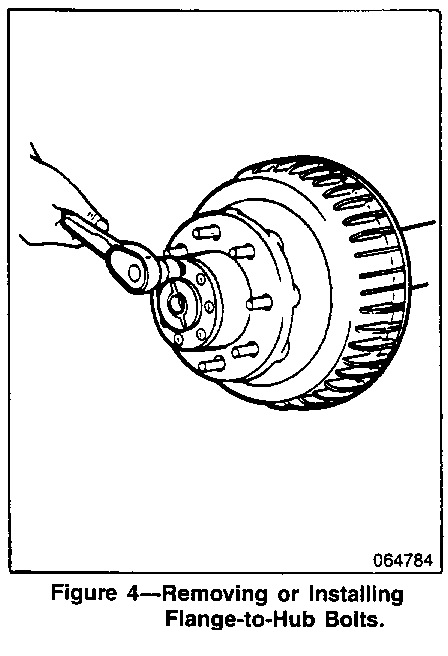
3. Remove axle shaft cap-to-hub bolts (Fig. 4) . Rap axle shaft flange lightly with a soft faced hammer to loosen shaft (not pictured). Grip rib on axle shaft flange with a locking plier and twist to start shaft removal. Remove axle shaft from tube (Fig. 1, 11) and remove old RTV or gasket. Clean axle shaft flange and outside face of hub (Fig. 1, 12).
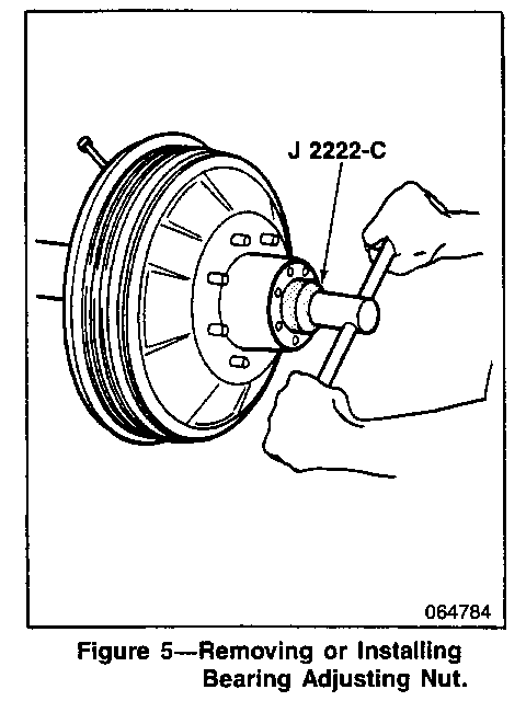
4. Remove outer locknut (Fig. 1, 1) using tool J 2222-C. Also, remove lock washer (Fig. 1, 2), adjusting nut (Fig. 1, 3) and washer (Fig. 1, 4) from axle tube (Fig. 5). Inspect and replace as necessary.
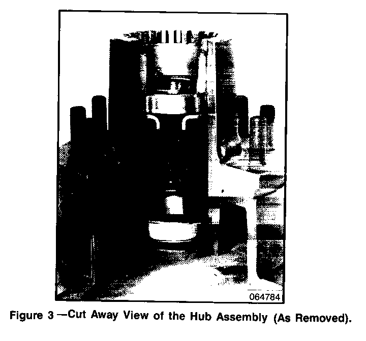
5. Remove hub (Fig. 1, 12) and lay it on a flat surface with a shop towel underneath to catch bearing and oil seal and to keep hub from collecting dirt, if disassembly is required. Check inside of hub for missing retaining ring (Fig. 1, 7) by looking from inner bearing (Fig. 1, 8 & 9) toward outer bearing (Fig. 1, 5 & 6) inside hub (Fig. 3). Retaining ring should be seated in groove against inner surface of outer bearing. If retaining ring is present perform Procedure C, otherwise perform Procedure D.
C. RETAINING RING NOT MISSING
1. Reinstall hub (Fig. 3) to axle tube (Fig. 1, 11) . Make sure bearings and oil seal (Fig. 1, 10) are positioned properly. Apply a light coat of high melting point EP bearing lubricant to contact surfaces and outside of axle tube. Refer to "Maintenance and Lubrication" in Section 0B of 1990 or 1991 Service Manual.
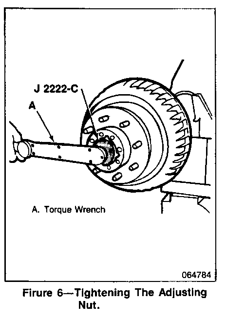
2. Reinstall washer (Fig. 1, 4) and adjusting nut (Fig. 1, 3). Tighten adjusting nut to 68 Nm (50 lb. ft.) using J 2222-C while rotating hub assembly, making certain bearing cones are seated and in contact with spindle shoulder (Fig. 6). To adjust the adjusting nut, back it off and retighten to 41-54 Nm (30-40 lb. ft.) while hub is rotated. Back off adjusting nut (Fig. 1, 3) 135 to 150 Degrees.
3. Reinstall lockwasher (Fig. 1, 2) and bend one tang of lockwasher over a flat of adjusting nut (Fig. 1, 3), 30 degrees minimum.
4. Reinstall outer locknut (Fig. 1, 1) and tighten to 88 Nm (65 lb. ft.) minimum. Bend one tang of lockwasher (Fig. 1, 2 over a flat of outer nut, minimum 60 degrees.
5. Reinstall axle shaft (not pictured) using either a gasket or applying RTV. Be sure shaft splines mesh into differential side gear and align axle shaft cap holes with hub holes. Retighten bolts to 156 Nm (115 lb. ft.) and reconnect caliper/linings as specified in Section 5A2 of 1990 or 1991 Service Manual.
6. Reinstall wheel and tire assembly and lower vehicle.
7. Install Campaign Identification Label.
D. RETAINING RING MISSING
When visual inspection of hub (Fig. 3) indicates a missing retaining ring (Fig. 1, 7), the bearings and oil seal (Fig. 1, 10) must be disconnected and replaced in addition to having a new retaining ring installed.
Tools Required: J 8092 Driver Handle J 8608 Outer Pinion Bearing Cup Installer J 24426 Outer Wheel Bearing Cup Installer J 24427 Inner Wheel Bearing Cup Installer J 24428 Axle Shaft Seal Installer
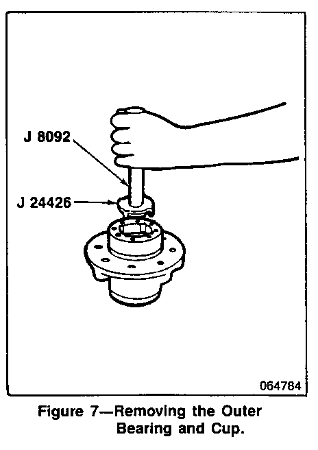
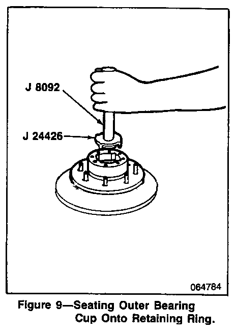
1. After laying hub (Fig. 3) on a flat surface with a shop towel to catch the bearing and oil seal, use a drift and remove inner bearing (Fig. 1, 9) and oil seal (Fig. 1, 10) . Also, remove outer bearing (Fig. 1, 5) using tool J 8092 with tool J 24426 to drive bearing (Fig. 1, 5) and cup (Fig. 1, 6) from hub (Fig. 7).
2. Clean lubricant from axle tube (Fig. 1, 11) and inside of hub (Fig. 1, 12), and inspect cups (Fig. 1, 6 & 8) for pits and cracks. Replace as necessary.
3. Pack new inner and outer bearings (Fig. 1, 5 & 9) with wheel bearing lubricant (P/N 1051344 or equivalent). Refer to "Maintenance and Lubrication" in Section 0B of 1990 or 1991 Service Manual.
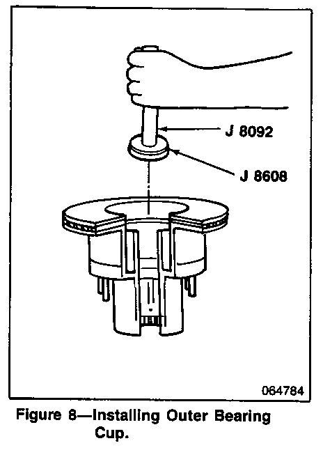
4. Using tools J 8092 and J 8608, install outer bearing cup (Fig. 1, 6) into hub (Fig. 1, 12). Drive cup into hub beyond retaining ring groove (Fig. 8).
NOTICE: Be certain tool J 8608 is installed upside down onto tool J 8092 so chamfer does not contact bearing cup (Fig. 1, 6).
5. Install retaining ring (Fig. 1, 7) into grove and drive outer bearing cup (Fig. 1, 6) back onto the retaining ring using tool J 24426 (Fig. 9).
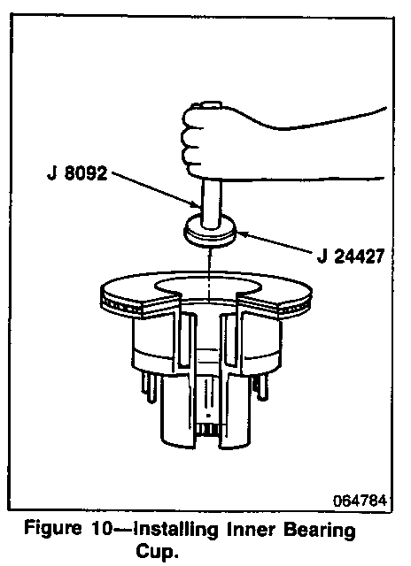
6. Install the inner bearing cup (Fig. 1, 8) using tools i 8092 and J 24427 (Fig. 10). Drive inner bearing cup into place until seated against hub shoulder.
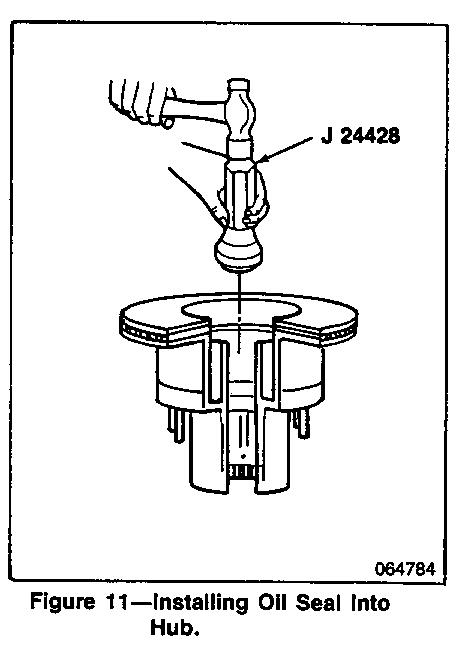
7. Install inner wheel bearing (Fig. 1, 9) and oil seal (Fig. 1, 10) using J 24428 (Fig. 11) , and also install outer wheel
8. Install hub (Fig. 1, 12) to axle tube (Fig. 1, 11) and adjust bearing preload as specified in Procedure C, "Retaining Ring Not Missing".
9. Install Campaign Identification Label.
CAMPAIGN IDENTIFICATION LABEL
Each vehicle corrected in accordance with the instructions outlined in this bulletin will require a "Campaign Identification Label". Each label provides a space to include the five (5) digit dealer code of the dealer performing the campaign service. This information may be inserted with a typewriter or a ball point pen.
Each "Campaign Identification Label" is to be located on the radiator core support in an area which will be visible when the vehicle is brought in for periodic servicing by the owner.
Apply "Campaign Identification Label" only on a clean, dry surface.
CLAIM INFORMATION
Submit a Product Campaign Claim with the information indicated below:
Labor Operation *Time Trouble Number Description Allowance Code ---------------- ------------------- ---------- -------- V6640 Inspect Hub Assy. 2.0 Hrs 96
Replace Bearings As Required
* For dealer to receive Administrative Time Allowance associated with this Campaign, add 0.1 hour to the Labor Operation Time Allowance.
Dealers will automatically receive the correct labor and material allowance based on the labor operation performed.
Refer to the GMC Truck Claims Processing Manual for details on Product Campaign Claim Submission.
Dear GMC Truck Owner:
This notice is sent to you in accordance with the requirements of the National Traffic and Motor Vehicle Safety Act.
REASON FOR THIS RECALL
General Motors has determined that certain 1990-91 GMC Truck P30 Motorhome Chassis fail to conform to the requirements of Federal Motor Vehicle Safety Standard (FMVSS) 105, "Hydraulic Brake Systems". These vehicles, equipped with 4.63 ratio Dana model 80 rear axles, heavy duty chassis, and 4-wheel disc brakes may have a missing rear axle outer bearing retaining ring and/or greater than specified bearing end play. Either of these conditions will allow the wheel rotor and hub assembly to shift relative to the spindle. This movement can cause the brake caliper piston to recede farther than normal into the piston bore which would require greater than normal brake fluid displacement when the service brakes are applied. Should this occur at a time when minimum stopping distance is required, it could result in a vehicle crash, without warning.
WHAT WE WILL DO
To correct this condition, your vehicles will have both rear axle hubs inspected for the condition(s) and corrected if necessary. This service will be performed for you at no charge.
WHAT YOU SHOULD DO
Please contact your GMC Truck dealer as soon as possible to arrange a service date and so the dealer may order the necessary parts for the repair. Instructions for making this correction have been sent to your dealer and parts are available. The labor time necessary to perform this service inspection/correction is approximately 2 hours. Please ask your dealer if you wish to know how much additional time will be needed to schedule and process your vehicle.
Your GMC Truck dealer is best equipped to obtain parts and provide service to ensure that your vehicle is corrected as promptly as possible. If, however, you take your vehicle to your dealer on the agreed service date, and they do not remedy this condition on that date or within five (5) days, we recommend you contact the GMC Truck Customer Assistance Center by calling 1-800-222-1020.
After contacting your dealer and the Customer Assistance Center, if you are still not satisfied that we have done our best to remedy this condition without charge and within a reasonable time, you may wish to write the Administrator, National Highway Traffic Safety Administration, 400 Seventh Street, S.W., Washington, D.C. 20590 or call 1-800-424-9393 (Washington D.C. residents use 366-0123).
The enclosed owner reply card identifies your vehicle. Presentation of this card to your dealer will assist in making the necessary inspection/correction in the shortest possible time. I f you have sold or traded your vehicle, please let us know by completing the postage paid reply card and returning it to us.
We are sorry to cause you this inconvenience; however, we have taken this action in the interest of your safety and continued satisfaction with our products.
General Motors bulletins are intended for use by professional technicians, not a "do-it-yourselfer". They are written to inform those technicians of conditions that may occur on some vehicles, or to provide information that could assist in the proper service of a vehicle. Properly trained technicians have the equipment, tools, safety instructions and know-how to do a job properly and safely. If a condition is described, do not assume that the bulletin applies to your vehicle, or that your vehicle will have that condition. See a General Motors dealer servicing your brand of General Motors vehicle for information on whether your vehicle may benefit from the information.
