AUTO APPLY PARKING BRAKE DIAGNOSIS

SUBJECT: AUTOMATIC APPLY PARKING BRAKE (INFORMATION AND DIAGNOSIS)
VEHICLES AFFECTED: 1990 P3 MOTORHOME (16000 #GVW ONLY)
The parking brake system on the 1990 16,000 pound GVW P3 Motorhome chassis incorporates a unique automatic apply feature with an internal expanding parking brake. The system is different than the 1989 and 1991 systems of the same model. The parking brake is spring applied and hydraulically released. Hydraulic pressure is supplied by the power steering pump. Full brake disengagement requires that 95-115 PSI pressure exists at the brake actuator.
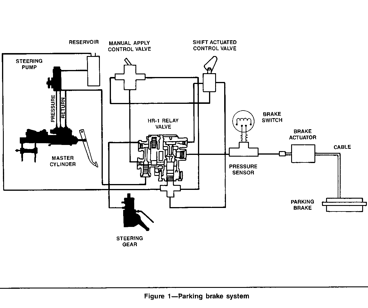
The parking brake can be applied by using a hand button or automatically when the shift lever is in the park position. The system features an HR-1 relay valve serving as a flow control point. The HR-1 reduces and directs flow to and from a spring actuator operating the parking brake, as shown in Figure 1.
Operational Features
1. In the event the vehicle stalls, the wheels can be spun freely for at least ten minutes until pressure is drained from the brake actuator and the spring brake reapplies.
2. A parking brake light in the vehicle warns the operator when the brake is applied. This brake light will come on when the pressure at the actuator is less than 60 PSI.
Parking Brake Adjustment
1. Adjusting the brake-to-drum clearance.
- Adjust screw through the drum opening until the brake just locks up.
- Back off the adjuster two to four notches.
- Drum should spin free with only light drag.
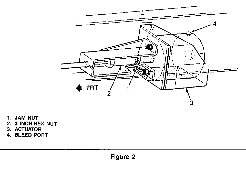
2. Adjusting the cable free play, refer to Figure 2.
- Loosen the jam nut towards the brake actuator.
- Turn the 3-inch-long hex nut along the stud until no free play exists.
- Move the jam nut until it is against the 3-inch-long hex nut.
- The actuator should stroke between .75 and 1.00 inch when properly adjusted.
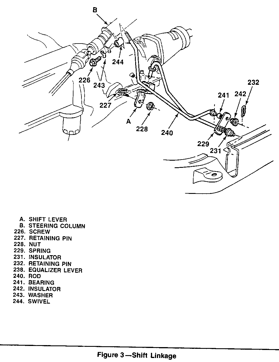
3. Adjust the transmission linkage, as shown in Figure 3.
- Apply the parking brake.
- Loosen the screw (226).
- Put the column selector lever in the neutral position. Put the lever into the neutral gate, do not use the indicator to find the neutral position.
- To put the transmission in neutral move the shift lever (A) to put the forward position, then back to the second detent.
- Hold the rod (240) tightly in the swivel (244). Tighten the nut (226) to 23 N.m (17 ft.lbs.).
Put the column selector lever in the "P" (park) position.
- Check the adjustment. The column selector lever must go into all positions. The engine must start in the "P" (park) or "N" (neutral) positions only.
Bleed Procedure I
1. Fill the power steering pump fluid reservoir to the proper level and let the fluid settle for at least a few minutes.
2. Start the engine and let it run for a few seconds; then turn off the engine.
3. Add fluid, if necessary.
4. Repeat the above procedure until the fluid level remains constant after running the engine.
5. Block the rear wheels or raise them off the ground.
6. Raise the front of the vehicle so the wheels are off the ground.
7. Start the engine, put the transmission in neutral, and place the park apply button in the release position. Slowly turn the steering wheel right and left, slightly contacting the wheel stops.
8. Check the fluid level and add fluid, if necessary.
9. Lower the vehicle and turn the steering wheel slowly from lock to lock.
10. Stop the engine. Check the fluid level and refill as required.
11. If the fluid is extremely foamy, allow the vehicle to stand a few minutes and repeat the above procedure.
12. If air still remains in the system, proceed on to bleed procedure 2.
Bleed Procedure 2
1. Secure the vehicle.
2. With the engine running, move the shift lever from the park to the neutral position.
3. Back off the bleed nut on the actuator and allow the system to self-bleed.
4. Tighten the actuator bleed part and cycle the system.
5. If air still remains in the system, proceed on to bleed procedure 3.
Bleed Procedure 3
1. Secure the vehicle.
2. Crack open the exhaust fitting of the manual control valve.
3. Engage the parking brake using the manual control valve.
4. Allow a small amount of fluid to bleed out of the fitting, then quickly tighten the fitting.
5. Repeat bleed procedures 1-3, as required.
Replacing the HR-1 Relay Valve
1. Removal
- Block the wheels and shut off the engine.
- Disengage the parking brake by running the actuator arm nut down against the bracket retaining the stud in a released position.
- Mark all lines and fittings.
- Remove all lines from the HR-1.
2. Installation
- Connect all lines to the HR-1. Be careful to use the marks made upon removal.
- Check fluid in reservoir.
- Perform system tests outlined in this Service Bulletin.
- Move the jam nut until it is against the 3-inch-long hex nut.
3. Adjusting the transmission linkage.
- Refer to the Service Manual. 1990 R/V,G,P models 7Al-55 shift linkage adjustment.
HR-1 Relay Valve Bleeding Procedure 2
- Secure the vehicle.
- With the engine running, move the shift lever from the park to the neutral position.
- Open the port on the actuator and allow the system to self- bleed.
- Tighten the actuator bleed port and cycle the system.
- If a whine noise can be heard, air still remains in the system; proceed on to Bleeding Procedure 2.
HR-1 Relay-Valve Bleeding Procedure 2
- Secure the vehicle.
- Crack open the exhaust fitting of the manual control valve.
- Engage the parking brake using the manual control valve.
- Allow a small amount of fluid to bleed out of the fitting; then quickly tighten the fitting.
- If air still remains in the system, bleed the power steering system as described in the Service Manual.
DIAGNOSTIC INFORMATION:
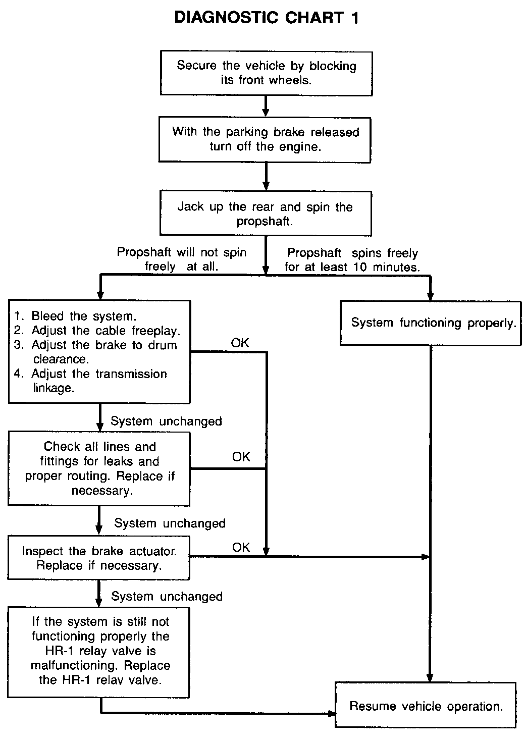
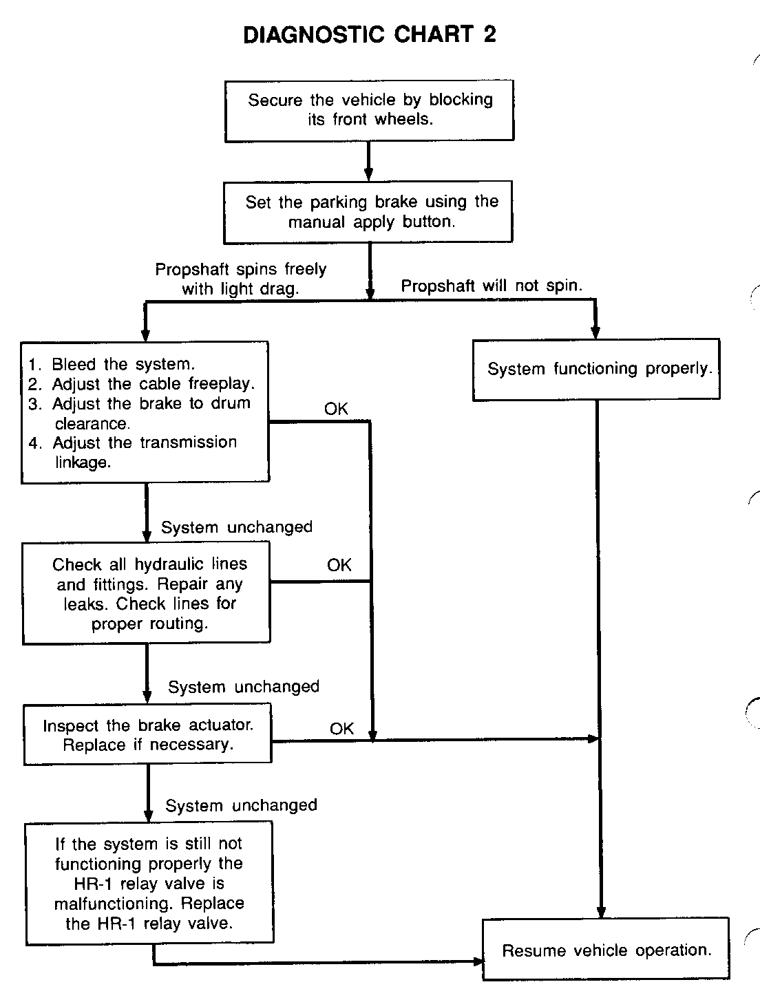
The following Diagnostics Charts 1 and 2 can be used to to determine if the Automatic Apply Parking Brake System is functioning normally and to identify what repairs may be required.
General Motors bulletins are intended for use by professional technicians, not a "do-it-yourselfer". They are written to inform those technicians of conditions that may occur on some vehicles, or to provide information that could assist in the proper service of a vehicle. Properly trained technicians have the equipment, tools, safety instructions and know-how to do a job properly and safely. If a condition is described, do not assume that the bulletin applies to your vehicle, or that your vehicle will have that condition. See a General Motors dealer servicing your brand of General Motors vehicle for information on whether your vehicle may benefit from the information.
