HYDRAULIC PARK BRAKE VALVE SEAL LEAK (REPLACE SEAL)

SUBJECT: HYDRAULIC FLUID/LEAKING HYDRAULIC PARK BRAKE VALVE SEAL (SEAL REPLACEMENT)
VEHICLES AFFECTED: 1990 P3 16000# MOTOR HOME (RPO C7P)
Some owners of 1990 P3 16000# motor homes may experience a condition where the hydraulic park apply control valve leaks hydraulic fluid. This does not affect the parking brakes while they are applied. The cause may be an undersized 0-ring which allows the fluid to pass out of the valve and/or a cap nut with insufficient thread which results in insufficient torque. For vehicles with the above condition, the 0-ring and cap nut should be replaced and threaded surfaces torqued to the specifications listed below. Additional parts are provided in the repair kit and should be used if necessary.
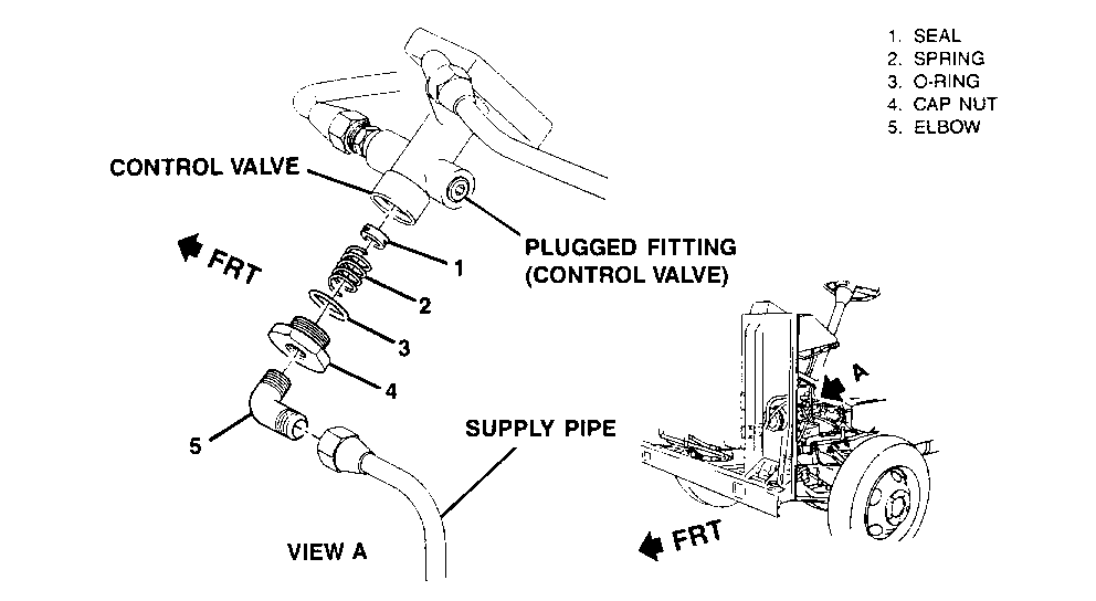
Note: Excessive torquing of the cap nut as shown in Figure 1, View A, #4) may result in the crushing of the bottom portion of the control valve.
SERVICE PROCEDURE: Refer to Figure 1
1. Place transmission in park position, set manual apply park brake by putting manual control knob in the on position. Leave the ignition in the off position. Put blocks on wheels.
2. Detach the left front wheel well panel. Retain all fasteners and panel for the reinstallation process. Locate the control valve (Figure 1). Prepare the removal area by having a towel or rag available to catch any oil leakage from the pipe/valve during removal.
3. Detach the supply pipe assembly at the elbow fitting (#5). Gently move pipe out of area to facilitate removal of the cap nut (#4) and elbow (Figure 1, View A, #5). The seal (#3) may not drop out due to oil viscosity; it may be necessary to use a thin pick to dislodge the seal (#3) from inside valve. Disconnect elbow from cap nut.
4. Prior to assembly, lubricate bores, 0-ring, and threads with lubriplate (P/N 1050109) or equivalent. Install replacement 0-ring (#3) over replacement cap nut (#4); place spring (#2) on inner pocket of cap nut (#4) and rest seal (#l) on top of the spring (#2). Balancing this assembly, gently raise into the valve body. Upon making contact with the valve, hand tighten assembly. Then torque cap nut (4) to 6-16 N.m. (5-12 ft.lbs.) in proper alignment with supply pipe.
5. Apply thread sealant to threads going into cap nut (#4) and threaded surface of elbow (#5). Thread elbow (#5) into cap nut (#4) and torque elbow to 12-14 N.m. (9-10 ft.lbs.). The final alignment of the elbow (#5) should be in the same direction as the plugged fitting located above the elbow (#5). CAUTION: Do not apply sealant over the elbow opening.
6. Reattach the supply pipe by gently bending it back into position; insert pipe into the elbow (#5) and torque the nut to 12-14 N.m. (9-10 ft.lbs.).
NOTE: To maintain proper fluid level throughout the bleed procedure, check and fill the power steering reservoir as necessary with power steering fluid (P/N 1050017).
7. Leaving vehicle transmission in park position, bleed system by starting vehicle and allowing 30 seconds to elapse; then loosen the supply pipe nut just enough to allow air to escape the system. Prepare the area by having a towel or rag available to catch any oil leakage. When leakage occurs, retorque supply pipe nut to 12-14 N.m. (9-10 ft.lbs.). Put the manual control knob in "OFF" position, crack delivery ("DEL") fitting on manual control valve to bleed. Release and set the manual apply park brake six times to help the bleeding process. Retorque delivery fitting of manual control valve. Turn off engine; inspect valve and fitting for leakage; tighten as required.
8. Retrieve and reinstall retained fasteners and wheelhouse panel that were detached in Step 2.
SERVICE PARTS INFORMATION:
Part Number Description Quantity -------- ---------------- ----------- 15680238 Seal Repair Kit 1 1050109 Lubriplate As Required 1050017 Power Steering Fluid As Required NPN Teflon Tape As Required
NOTE: Labour Operation is coded to base vehicle coverage in the warranty system.

General Motors bulletins are intended for use by professional technicians, not a "do-it-yourselfer". They are written to inform those technicians of conditions that may occur on some vehicles, or to provide information that could assist in the proper service of a vehicle. Properly trained technicians have the equipment, tools, safety instructions and know-how to do a job properly and safely. If a condition is described, do not assume that the bulletin applies to your vehicle, or that your vehicle will have that condition. See a General Motors dealer servicing your brand of General Motors vehicle for information on whether your vehicle may benefit from the information.
