CAMPAIGN:CLUTCH/FLYWHEEL HOUSING CRACKS

SUBJECT: CLUTCH/ FLYWHEEL HOUSING CRACKS
MODELS: 1992-93 P3(42) WITH NP4500 (RPO MT8) MANUAL TRANSMISSIONS, 6.2L DIESEL ENGINES (RPO LL4) WITH TRANSMISSION MOUNTED PARK BRAKE DRUM (JF9)
THIS BULLETIN HAS BEEN REVISED TO UPDATE THE WARRANTY INFORMATION SECTION. DISCARD ALL COPIES OF 93-C-24.
General Motors has determined that CERTAIN 1992-93 P3 (42) Models may exhibit cracking of the Aluminum Clutch Housing. This condition could result in severe vibrations.
To correct this condition, the Aluminum Clutch Housing Assembly will be replaced with a new Cast-Iron Housing Assembly.
VEHICLES INVOLVED
Involved are CERTAIN 1992-93 P3(42) built within the following VIN breakpoints. (There are only 73 vehicles involved in this campaign for GMC Truck.)
Year Model From Through
1992 P3(42) W/LL4 & SOP EOP MT8 & JF9 1993 P3(42) W/LL4 & SOP EOP MT8 & JF9
The specific vehicles involved in this campaign have been identified by Vehicle Identification Number Computer Listings. These listings are furnished to all involved dealers with the campaign bulletin. Dealers should confirm vehicle eligibility through VISS (Vehicle Information Service System) or SERVICENET prior to beginning campaign repairs.
DEALER CAMPAIGN RESPONSIBILITY
All unsold vehicles in dealers' possession and subject to this campaign MUST be held and inspected/repaired per the service procedure of this campaign bulletin BEFORE owners take possession of these vehicles.
Dealers are to service all vehicles subject to this campaign at no charge to owners, regardless of mileage, age of vehicle, or ownership, from this time forward.
Owners of vehicles recently sold from your vehicle inventory are to be contacted by the dealer and arrangements made to make the required correction according to instructions contained in this bulletin.
In summary, whenever a vehicle subject to this campaign enters your vehicle inventory, or is in your dealership for service in the future, please take the steps necessary to be sure the campaign correction has been made before selling or releasing the vehicle.
If the name and address of the owner of an involved vehicle was unavailable to GMC Truck Division at the time of campaign initiation, the dealer must determine the owner's name and address from the dealership sales records. Please provide this information directly on the second copy of the listing next to the applicable VIN so that our records may be updated and the appropriate notification mailed to the owner. This second copy should then be submitted to the address listed below in the previously supplied yellow campaign envelopes.
GMC Truck Division General Motors Corporation 101 Union Street Plymouth, Michigan 48170
OWNER NOTIFICATION
Owners will be notified of this campaign on their vehicles by GMC Truck Division (see copy of owner letter included with this bulletin). A listing of owner names and addresses has been furnished to the involved dealers to enable dealers to follow up with owners involved in this campaign. This listing may contain owner names and addresses obtained from State Motor Vehicle Registration records. The use of such motor vehicle registration data for any other purpose is a violation of law in several states. Accordingly, you are urged to limit the use of this listing to this campaign.
SERVICE PROCEDURE
1. Remove negative battery cable. Be sure that the ignition switch is in the "OFF" or "LOCK" position when doing this.
2. Remove engine cover.
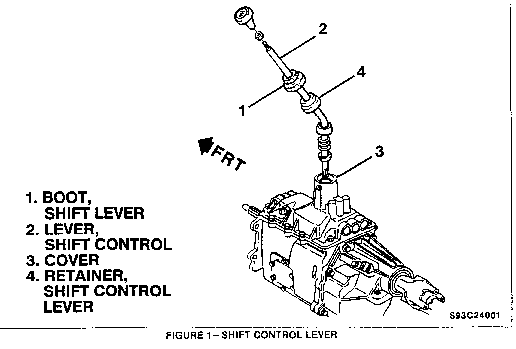
3. Raise shift lever boot (Figure 1, item 1) on the shift control lever (Figure 1, item 2).
4. Remove shift control lever (Figure 1, item 2) from the cover (Figure 1. item 3). Use Shift Lever Retainer Remover and Installer (Kent Moore tool J39917) to push the shift control lever retainer (Figure 1. item 4) down and turn to the left.
5. Raise the vehicle and support with safety stands.
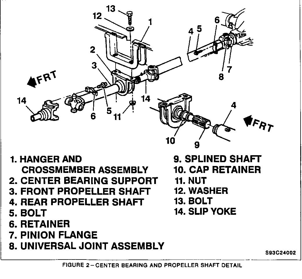
6. Reference mark the front propeller shaft (Figure 2, item 3) to the transmission slip yoke (Figure 2, item 14). Reference mark the rear propeller shaft (Figure 2, item 4) to both the pinion flange (Figure 2, item 7) and the front propeller shaft (Figure 2, item 3).
7. Loosen cap retainer (Figure 2, item 10) at the center bearing support (Figure 2, item 2).
8. Remove bolts and retainers (Figure 2, items 5 and 6) at the pinion flange and remove propeller shaft from the flange. Tape bearing cups onto yoke and U-joints to prevent loss of the needle bearings.
9. Remove rear propeller shaft (Figure 2, item 4). Slide propeller shaft forward to disengage rear U-joint (Figure 2, item 8) from pinion flange. Then slide shaft rearward off front propeller shaft (Figure 2, item 3) splines.
10. Remove bolts and retainers (Figure 2, items 5 and 6) at the transmission slip yoke (Figure 2, item 14).
11. Remove bolts, washers and nuts (Figure 2, items 13, 12 and 11) from center bearing support (Figure 2, item 2). Set aside.
12. Remove front propeller shaft (Figure 2, item 3) with center bearing support (Figure 2, item 2) from the vehicle and set aside.
13. Remove park brake cable.
14. Remove wiring harness clip nut and electrical wiring harness from the transmission.
15. Securely support the transmission and engine.
16. Remove hanger and cross member assembly (Figure 2, item 1) as necessary.
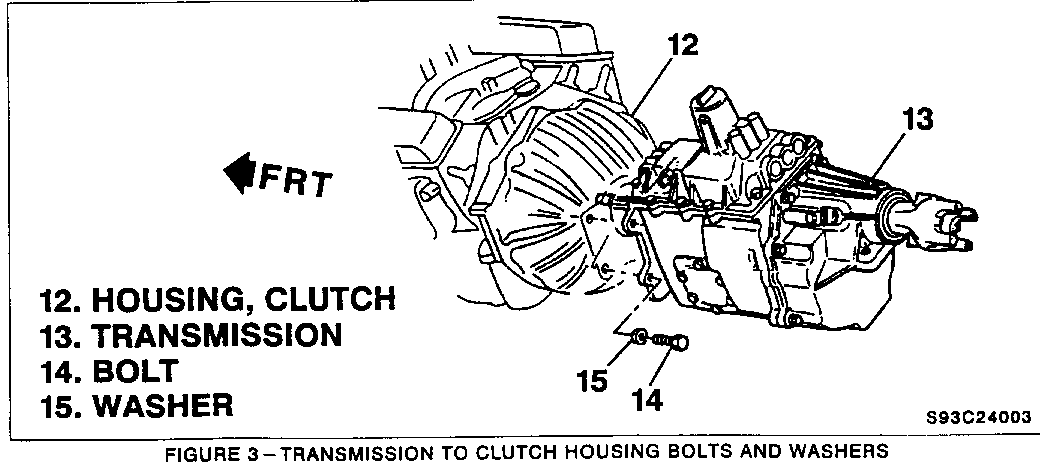
17. Remove transmission (Figure 3, item 13) to clutch housing bolts and washers (Figure 3, items 14 and 15).
18. Remove transmission (Figure 3, item 13) from the clutch housing (Figure 3, item 12) and set transmission aside.
IMPORTANT: Do not let the transmission hang from the clutch. Pull the transmission straight back on the clutch hub splines.
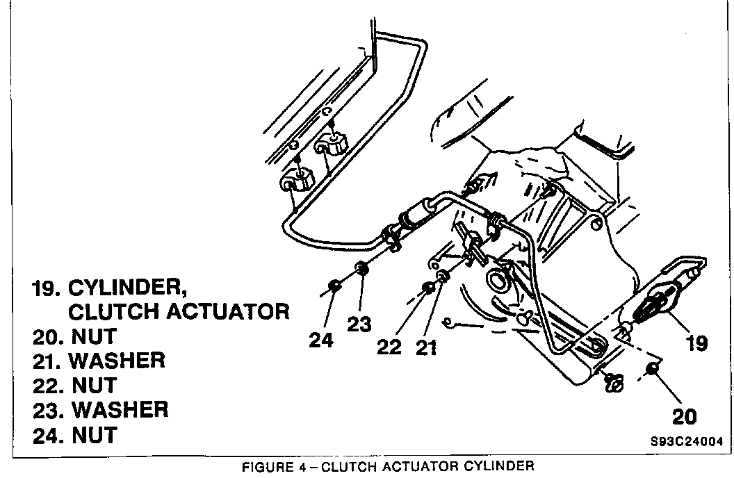
19. Remove clutch actuator cylinder (Figure 4, item 19) to clutch housing nuts (Figure 4, items 20, 22 and 24) and washers (Figure 4, items 21 and 23).
20. Remove clutch actuator cylinder (Figure 4, item 19) from the clutch housing and set aside.
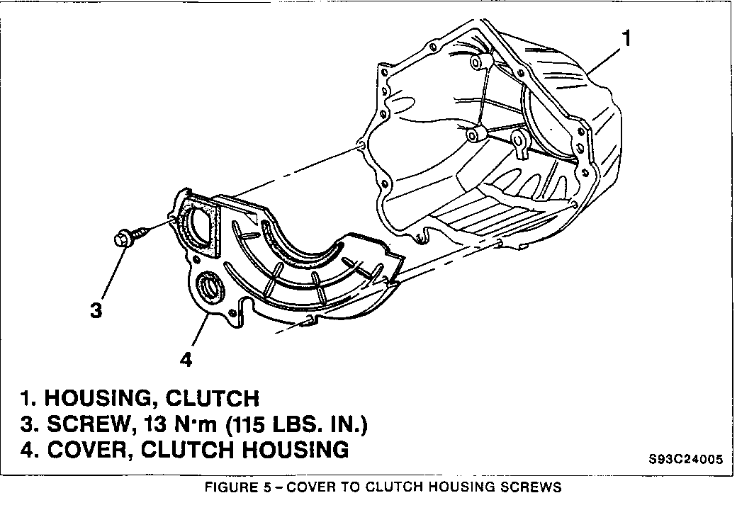
21. Remove clutch housing cover (Figure 5, item 4) to clutch housing screws (Figure 5, item 3).
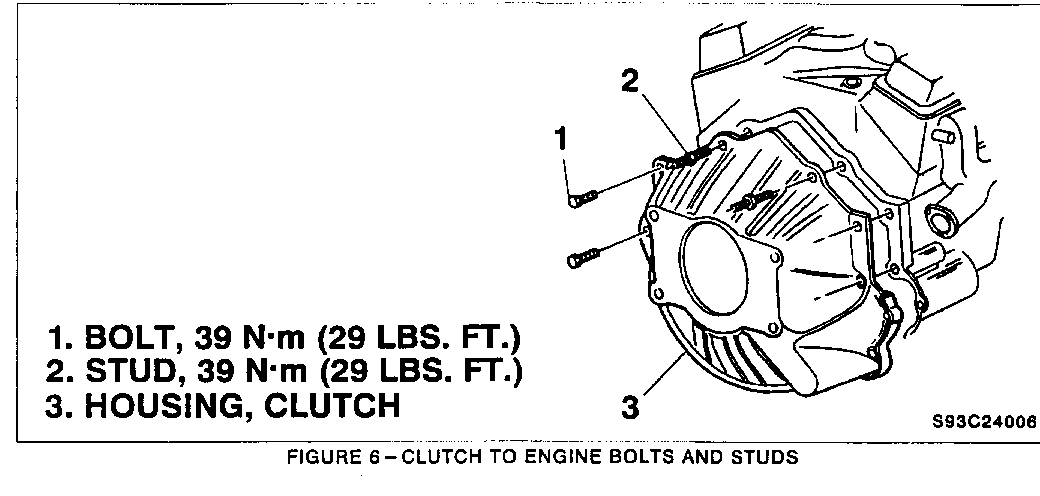
22. Remove clutch housing (Figure 6, item 3) to engine bolts and studs (Figure 6, items 1 and 2).
23. Remove clutch housing (Figure 6, item 3) from the engine.
24. Install new Cast Iron Clutch Housing Assembly (GM P/N 15985420) to the engine bolts with studs (Figure 6, items 1 and 2). Be sure electrical wiring harness is clear of engine and clutch housing interface. Tighten clutch housing bolts and studs to 39 Nm (29 lbs. ft.).
25. Install clutch housing cover (Figure 5, Item 4) to clutch housing screws (Figure 5, Item 3). Torque cover screws to 13 Nm (10 lbs. ft.).
26. Install clutch actuator cylinder (Figure 4, item 19) to the clutch housing. Torque actuator cylinder nuts to 17 Nm (13 lbs. ft.).
27. Shift transmission into gear before reinstalling.
28. Install transmission (Figure 3, item 13) to the clutch housing (Figure 3. item 12). Torque bolts to 100 Nm (74 lbs. ft.). Remove the jack from underneath the transmission.
29. Install hanger and cross member assembly (Figure 2, item 1) as necessary.
30. Install electrical wiring harness and wiring harness clip nut. Torque harness clip nut to 27 Nm (20 lbs. ft.).
31. Install park brake cable.
32. Install front propeller shaft (Figure 2, item 3) up against transmission slip yoke (Figure 2. item 14) and install retainers and bolts (Figure 2, items 6 and 5), lining up reference marks. Torque bolts to 28 Nm (21 lbs. ft.). Be sure to remove tape from bearing cups before reinstalling propeller shaft.
33. Install center bearing support (Figure 2, item 2) using bolts, washers and nuts (Figure 2, items 13, 12 and 11) to hanger and cross member assembly (Figure 2, item 1).
34. Install rear propeller shaft (Figure 2, item 4). lining up reference marks. Slide the front end of the shaft onto the splined shaft (Figure 2, item 9) of the front propeller shaft (Figure 2, item 3). Slide it far enough forward to allow the rear U-Joint (Figure 2, item 8) to engage the pinion flange (Figure 2, item 7).
35. Set splined shaft seal (Figure 2, item 9) in place and secure cap retainer (Figure 2, item 10) onto rear shaft (Figure 2, item 4).
36. Install bolts and retainers (Figure 2, items 5 and 6) at the pinion flange (Figure 2, item 7). Torque bolts to 44 Nm (33 lbs. ft.).
37. Remove safety stands and lower the vehicle.
38. Install shift control lever to the cover (Figure 1, items 2 and 3). Use Shift Lever Retainer Remover and Installer (Kent Moore tool J39917) to push the retainer (Figure 1, item 4) down and tum to the right.
39. Install shift lever boot (Figure 1, item 1).
40. Install engine cover.
41. Connect negative battery cable. Be sure that the ignition switch is in the "OFF" or "LOCK" position when doing this.
PARTS INFORMATION
Parts are to be obtained from General Motors Service Parts operation (GMSPO). To ensure parts are obtained as soon as possible, order them from GMSPO on a C.I.O. order with no special instruction code but order under an advise code (2).
Part Number Description Quantity ----------- ----------- -------- 15985420 Cast Iron Clutch Housing 1 Assembly
WARRANTY INFORMATION
Dealers should submit a warranty claim on each vehicle completed under this campaign.
Labor Operation *Time Trouble Number Description Allowance Code ----------------------------------------------------------------- V 8780 Clutch Housing 3.8 hrs. 96 Replace
* For dealer to receive Administrative Time Allowance associated with this campaign, add 0.1 hour to the Labor Operation Time Allowance.
CAMPAIGN IDENTIFICATION LABEL
Each vehicle corrected in accordance with the instructions outlined in this Product Campaign Bulletin will require a "Campaign Identification Label." Each label provides a space to include the campaign number and five (5) digit dealer code of the dealer performing the campaign service. This information may be inserted with a typewriter or ball point pen.
Each "Campaign Identification Label is to be located on the radiator core support in an area which will be visible when the vehicle is brought in for periodic servicing by the owner.
Apply "Campaign Identification Label" only on a clean, dry surface.
ADMINISTRATIVE PROCEDURE
Procedures covering this campaign are outlined in Section V of your dealership's "GMC Truck Warranty Claims Processing Manual" #P9119.
Dear GMC Truck Owner:
As a valued customer, your complete satisfaction with your GMC truck is our goal. In keeping with this goal, we want to let you know that we have discovered a problem that could affect your vehicle.
General Motors has determined that certain 1992-93 Commercial Chassis may exhibit cracking of the aluminum clutch housing. This condition could result in severe vibrations.
To prevent this from occurring on your vehicle, we will replace the aluminum clutch housing assembly with a new cast-iron housing assembly. This service will be performed for you at no charge.
Instructions for performing this service have been sent to your GMC Truck dealer, and parts are available. Please contact you GMC dealer to arrange a service date as soon as possible. This procedure will take about 4.0 hours to complete, but you should ask how much additional time your dealer will need to schedule and process your vehicle.
The enclosed postage paid owner reply card identifies your vehicle. Presentation of this card to your dealer will assist in making the necessary correction to your vehicle in the shortest possible time. If you have sold or traded your vehicle, please furnish us the complete name and address of the person you sold or traded your vehicle to and return the card to us.
We are sorry to cause you this inconvenience; however, we have taken this action in the interest of your continued satisfaction with our product.
GMC TRUCK DIVISION GENERAL MOTORS CORPORATION
General Motors bulletins are intended for use by professional technicians, not a "do-it-yourselfer". They are written to inform those technicians of conditions that may occur on some vehicles, or to provide information that could assist in the proper service of a vehicle. Properly trained technicians have the equipment, tools, safety instructions and know-how to do a job properly and safely. If a condition is described, do not assume that the bulletin applies to your vehicle, or that your vehicle will have that condition. See a General Motors dealer servicing your brand of General Motors vehicle for information on whether your vehicle may benefit from the information.
