Power Steering Gear Inlet and Outlet Hose Replacement Non Rack and Pinion
Removal Procedure
- Disconnect the energy storage box before serving the vehicle. Refer to Hybrid Battery Service Disconnect/Connect in Engine Electrical.
- Install a drain pan under the vehicle.
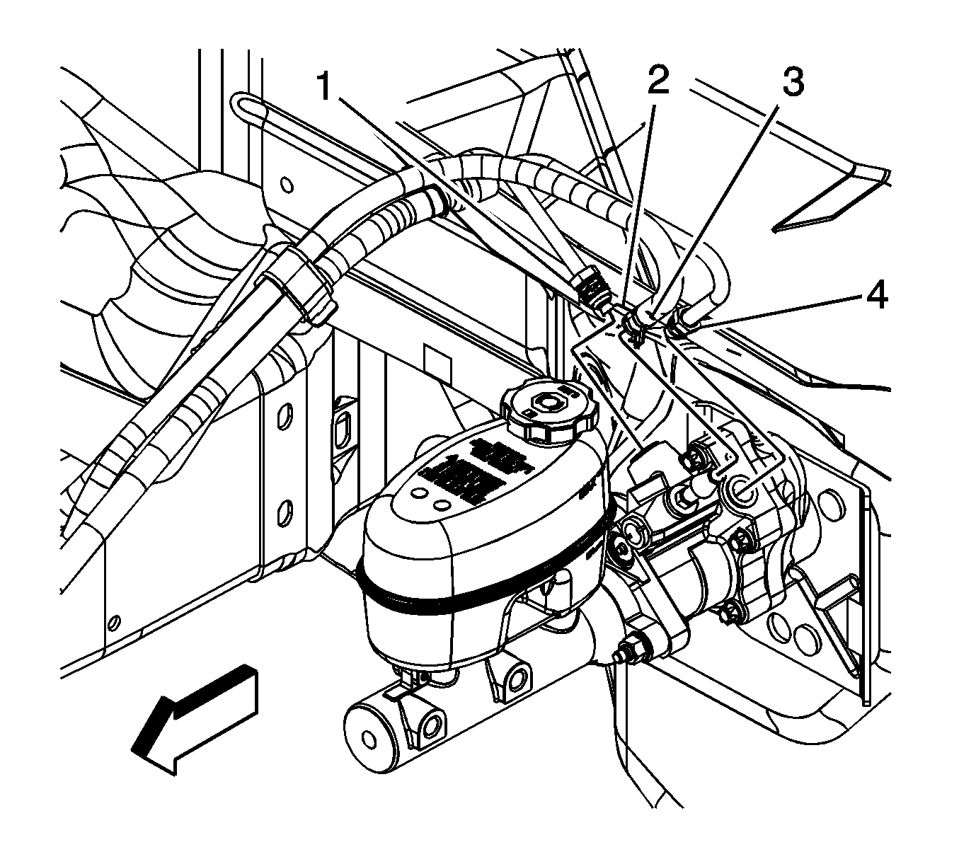
- Remove the power steering gear inlet hose (4) from the brake booster.
- Remove the power brake booster outlet hose (3) retaining clamp (2) to remove the power brake booster hose outlet hose from the brake booster.
- Remove the power brake booster inlet hose (1) from the brake booster.
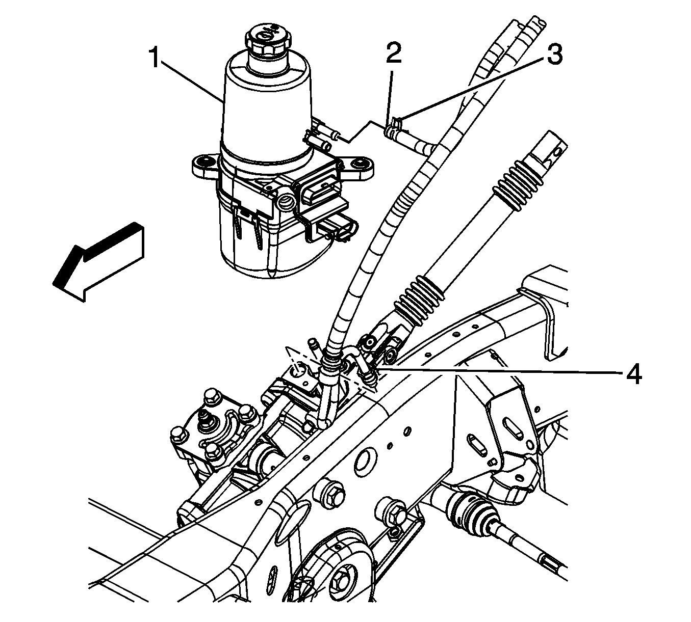
- Remove the power steering gear inlet hose (4) from the power steering gear.
- Remove the power brake booster outlet hose (2) retaining clamp (3) to remove the power brake booster outlet hose from the power steering pump.
- Remove the power brake booster inlet hose from the power steering pump.
- Remove the power steering hose assembly from the vehicle.
Notice: Do not start the vehicle with any power steering gear inlet or outlet hoses disconnected. When disconnected, plug or cap all openings of components. Failure to do so could result in contamination or loss of power steering fluid and damage to the system.
Installation Procedure
- Install the gear inlet hose to the gear (4).
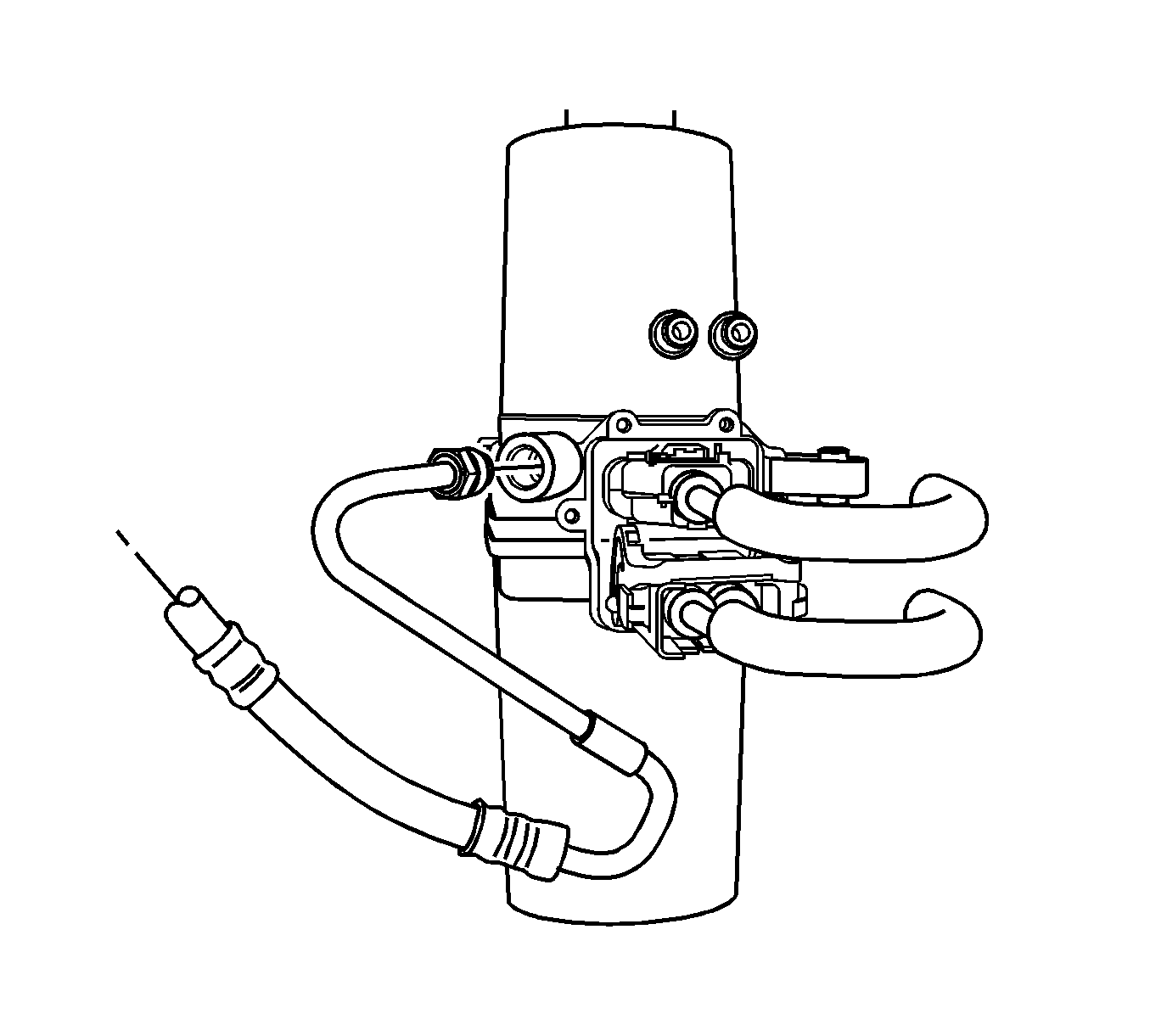
- Install the booster inlet hose to the pump.
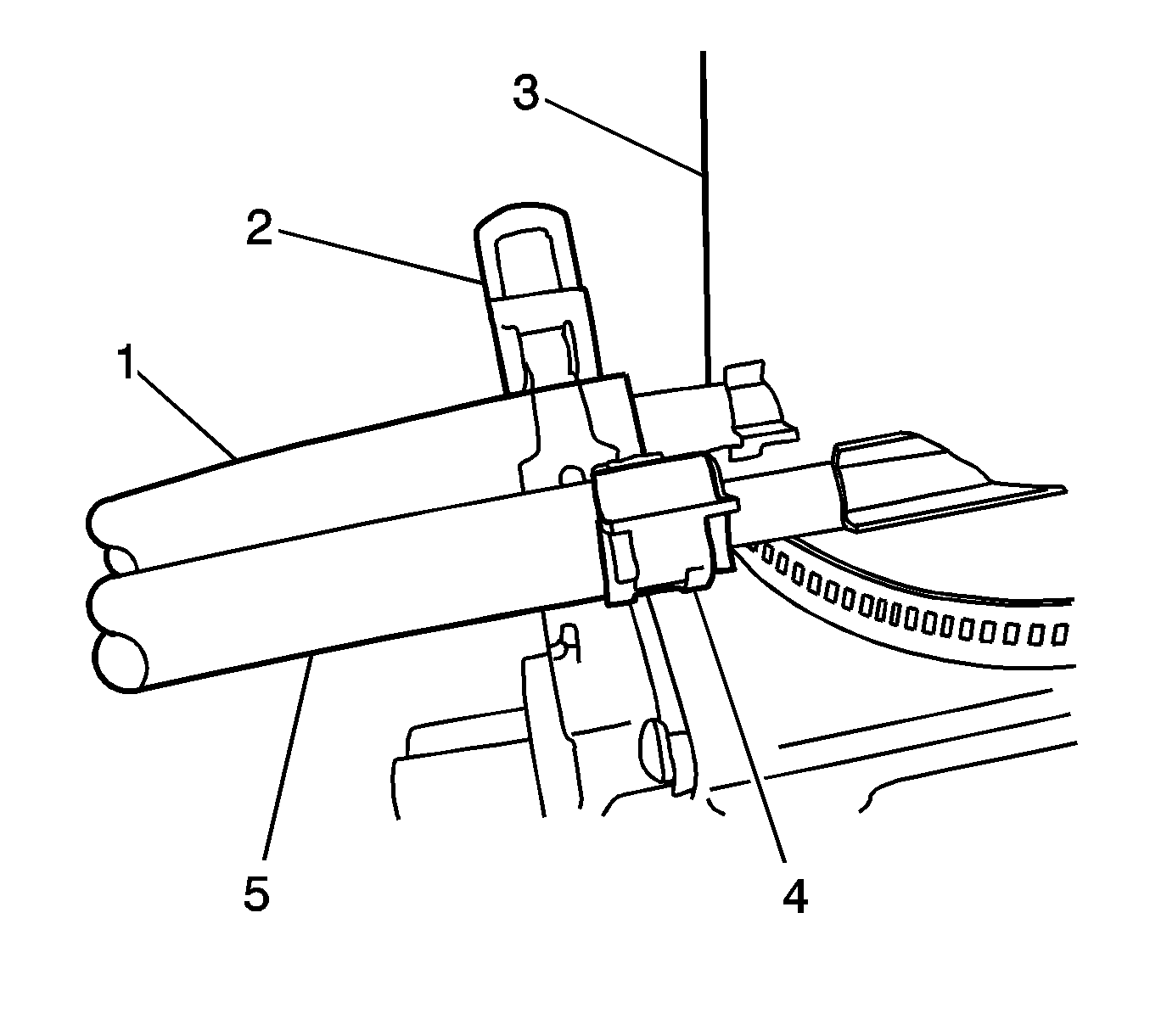
- Install the booster outlet hose to the power steering pump nipple (5) and retaining clamp.
- Install the booster inlet hose (1) to the booster.
- Install the gear inlet hose to the booster.
- Install the booster outlet hose (3) to the booster and install the retaining clamp (2).
- Remove the drain pan from under the vehicle.
- Bleed the power steering system. Refer to Power Steering System Bleeding .
- Connect the energy storage box after servicing the vehicle. Refer to Hybrid Battery Service Disconnect/Connect in Engine Electrical.

Notice: The inlet and outlet hoses must not be twisted during installation. Do not bend or distort the inlet or outlet hoses to make installation easier. Failure to follow these procedures could result in component damage.
Important: Following this sequence ensures correct routing and orientation.

Important: Ensure that the hose contacts the power steering pump as shown.

Notice: Refer to Fastener Notice in the Preface section.
Tighten
Tighten both power steering inlet hose fittings to 32 N·m (24 lb ft).
Power Steering Gear Inlet and Outlet Hose Replacement Rack and Pinion
Removal Procedure
- Disconnect the energy storage box before servicing the vehicle. Refer to Hybrid Battery Service Disconnect/Connect in Engine Electrical.
- Install a drain pan under the vehicle.
- Remove the power steering gear inlet hose (4) from the brake booster.
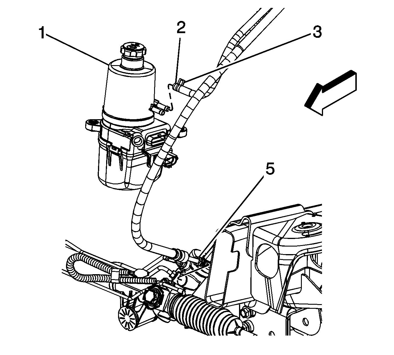
- Remove the power brake booster outlet hose (3) retaining clamp (2) to remove the power brake booster hose outlet hose from the brake booster.
- Remove the power brake booster inlet hose (1) from the brake booster.
- Remove the power steering gear inlet hose (5) from the power steering gear.
- Remove the power brake booster outlet hose (2) retaining clamp (3) to remove the power brake booster outlet hose from the power steering pump.
- Remove the power brake booster inlet hose (5) from the power steering pump.
- Remove the power steering hose assembly from the vehicle.

Notice: Do not start the vehicle with any power steering gear inlet or outlet hoses disconnected. When disconnected, plug or cap all openings of components. Failure to do so could result in contamination or loss of power steering fluid and damage to the system.
Installation Procedure
- Install the booster inlet hose to the pump.
- Install the gear inlet hose to the gear (5).
- Install the booster outlet hose to the power steering pump nipple and retaining clamp (2).
- Install the booster inlet hose (1) to the booster.
- Install the gear inlet hose to the booster.
- Install the booster outlet hose (3) to the booster and install the retaining clamp (2).
- Remove the drain pan from under the vehicle.
- Bleed the power steering system. Refer to Power Steering System Bleeding .
- Connect the energy storage box before after servicing the vehicle. Refer to Hybrid Battery Service Disconnect/Connect in Engine Electrical.
Notice: The inlet and outlet hoses must not be twisted during installation. Do not bend or distort the inlet or outlet hoses to make installation easier. Failure to follow these procedures could result in component damage.
Important: Following this sequence ensures correct routing and orientation.
Important: Ensure that the hose contacts the power steering pump as shown.


Notice: Refer to Fastener Notice in the Preface section.
Tighten
Tighten both power steering inlet hose fittings to 32 N·m (24 lb ft).
